


Structural fire engineering
Fire safety engineering can deliver value across the five areas of activity in the provision of fire precautions in buildings. These are:
- Means of warning and escape
- Internal fire spread
- Structural response
- External fire spread
- Access and facilities for the fire service
This article concentrates on the third of these, structural response. Of necessity, the information contained in these pages is not comprehensive. The reader’s attention is drawn in particular to guidance published by the Institution of Structural Engineers[1] for more detailed information. This document states that by adopting a performance based approach to structural fire engineering…more economic designs can be achieved and more innovative and complex buildings can be constructed.
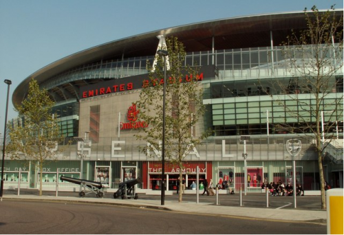

(Image courtesy of Andrew Dunn)
[top]Introduction
Guidance on the procedures for carrying out fire safety engineering analyses in buildings is contained in BS 7974[2]. The introduction to this standard describes its purpose as being: to provide a framework for developing a rational methodology for the design of buildings using a fire safety engineering approach, based on the application of scientific and engineering principles to the protection of people, property and the environment from fire. BS 7974[2] is accompanied by a series of published documents (PD 7974, Parts 1 to 7))[3] giving detailed guidance on the principles of fire engineering, fire development, spread of smoke, structural response, fire detection, fire service intervention, evacuation and risk assessment.
Fire safety engineering is applied across a wide range of building types. Typical of these is the design of sports stadia. Modern developments incur considerable investment and clients are seeking alternative means of attracting revenue on capital outlay. This means that some sports stadia can no longer be described as simple steel, concrete and blockwork structures for the sole purpose of watching sport. Instead they are mixed occupancy, often containing shops, restaurants and conference facilities. This can create difficulties in developing fire safety policies consistent with the objectives of the building regulations by the use of Government published guidance alone. This is acknowledged in Approved Document B [4] which states that: Fire safety engineering might provide an alternative approach to fire safety. Fire safety engineering may be the only practical way to achieve a satisfactory standard of fire safety in some complex buildings and in buildings that contain different uses.
In addition to sports stadia, typical structures commonly designed using modern fire safety engineering techniques include offices, industrial buildings, airport terminals, leisure centres, hospitals and shopping centres.
Fire safety engineering requires the co-operation of the entire design team if its full potential is to be realised and it is strongly advised that fire safety must be part of the remit of the team from the start of the design process. Structural engineers, fire engineers, architects, clients and representatives of the local authority need to communicate throughout the design process. The fire engineer must be given the opportunity to work closely with the architect and engineer to understand the features of the structure and to be able to communicate at the design stage the opportunities to facilitate a cost-effective solution to allow the development of advanced capability in fire.
[top]The stages of structural fire engineering
If the response of a structure in a fire is to be calculated, it is first necessary to identify realistic fire scenarios for the assumed compartment of origin. Following this the time-temperature relationship in the fire must be established. Only then is it possible to predict the temperature and response of the structure.
[top]Predicting the temperature of the compartment

The simplest way to predict the time-temperature relationship within a fire compartment is to assume a standard fire. This has the advantages of being simple and well understood.
An alternative method for predicting the heating rate and maximum temperature of the atmosphere inside the fire compartment involves assessing the fire load (the quantity and type of combustible material), the ventilation and the thermal characteristics of the compartment linings. These variables can be calculated or obtained from tabulated data. Once known, the temperature rise in the compartment with time can be determined. This is most commonly done in terms of a parametric time-temperature relationship although zone modelling and computational fluid dynamics are also used.
If the fire load, ventilation and thermal characteristics of the compartment linings are known, a time equivalent can be calculated (the exposure to a standard fire that would have the same effect as the natural fire in the compartment under consideration).
[top]Predicting the temperature of the structure
The temperature which the structure will reach in a fire will depends on the location, its size and any fire protection or shielding which may be in place. Where shielding and partial protection are not factors, the temperatures attained by individual unprotected and protected structural steel members can be determined using temperature growth rates and heat transfer relationships given in the fire Eurocodes: BS EN 1991-1-2[5] and BS EN 1993-1-2[6]. This is a complex calculation and is usually carried out using a spreadsheet approach, although it is also possible to use software based on finite difference or finite element analysis.
In BS 5950 Part 8[7] the temperatures attained by unprotected individual beams and columns in a standard fire test are also given in tabular format for fire ratings from 15 to 60 minutes.
In addition, temperatures can also be calculated for individual elements of structure or for frame assemblies using bespoke models calibrated against actual test results.
[top]Predicting the response of the structure
The response of the structure depends not only on the temperature it reaches in the fire but also on the applied loads and the effects of any composite action, restraint and continuity from the remainder of the structure. Once the response is known, fire protection requirements can be specified to meet the specific hazard. This design concept proves most cost effective when it can be demonstrated that the structure, or parts of the structure, has sufficient inherent fire resistance to avoid the need to apply fire protection .
[top]Parametric time-temperature relationships


Extensive research on fire growth and behaviour has led to the development of an approach for determining the parametric, or natural, time-temperature relationships which will develop within a compartment in the event of a fire. This has been consolidated in the fire Eurocodes, specifically Appendix A of BS EN 1991-1-2[5], which should be read in conjunction with the relevant National Annex[8]. The use of parametric time-temperature relationships enables the engineer to eliminate some of the limitations of the standard fire test. Most importantly, it allows the engineer to take into account the fact that real fires have a growth and decay phase and are not adequately characterised by the infinite temperature rise of the standard fire test.
[top]Time equivalent
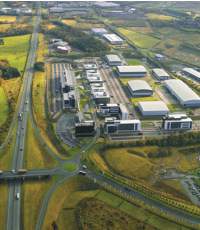

(Image courtesy of JGA Fire Engineering Consultants)
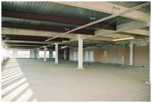
Time equivalent allows the engineer to calculate the severity of a fire in a compartment in terms of the standard fire time-temperature relationship. For example, should the engineer calculate that the time equivalent of a fire in a compartment was 45 minutes, this means that a fire in that compartment would be equivalent in severity to exposure to the standard fire test for that period of time. A number of formulae exist for the calculation of time equivalent, the most widely used of which is to be found in Appendix B of PD 6688-1-2[9]. As with the calculation of parametric time-temperature relationships, this links the fire severity to the key compartment parameters of ventilation, fire load density and wall characteristics. Time equivalent may be used to demonstrate that the tabulated fire resistance periods required in many large buildings (as given in Approved Document B[4], Scottish Technical Handbook 2022[10] in Scotland and Technical Booklet E[11] in Northern Ireland) are overly conservative and can be reduced.
The photograph shows Maxim Office Park, Eurocentral, outside Glasgow. This project incorporated 10 buildings, each designed as a single compartment of more than 4000m², requiring 120 minutes fire resistance according to Scottish Technical Handbook 2022[10]. An analysis taking into account ventilation conditions, fire load and surface linings showed that a real fire would be as severe as exposure to the standard fire test for between 26 and 28 minutes. A sensitivity analysis was carried out taking into account variations in the key parameters. Following this analysis, fire resistance periods of 60 minutes in nine buildings and 90 minutes in one building were adopted. More information is available in the case study at the bottom of this page.
[top]Cardington fire tests

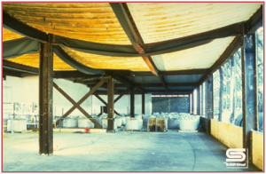

Modern structural fire engineering in steel framed buildings owes much to a series of seven fire tests which were carried out on an eight storey steel framed building with composite steel deck floors at the Building Research Establishment (BRE) facility at Cardington in Bedfordshire between 1994 and 2003. The test programme was divided into two parts; the first, comprising a single beam test and three large compartment tests was funded partly by British Steel and partly by the Research Fund for Coal & Steel (then the European Coal and Steel Community). A complementary program, comprising three compartment tests was carried out by the Building Research Establishment.
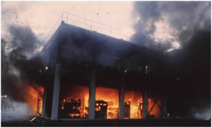
The tests were carried out to determine if the fire performance of real buildings with composite steel deck floors was better than is suggested by tests on individual elements of construction. Evidence that this was the case had been provided by fires in real building (including at the Broadgate development in London: see SCI P113), tests carried out in Australia and also small scale fire tests and computer modelling of structural behaviour. In all these cases, composite steel deck floors had demonstrated robustness and resistance to fire far greater than was indicated by standard fire tests on single beams or slabs.
In order to obtain a direct comparison with the standard fire tests, the first test was carried out on a single unprotected beam and surrounding area of slab. The steel temperatures and beam defections measured in the test indicated that a failure deflection would have occurred at a temperature over 1000°C, far greater than the temperature of 700°C at which it would have failed if tested in isolation.
Further tests were carried out in compartments varying in size from 50m² to 340m² with fire loadings provided by gas, wooden cribs and standard office furniture. Columns were protected but beams were not. Despite atmosphere temperatures of over 1200°C and temperatures on the unprotected steel beams of 1100°C in the worst case, no structural collapse took place.
The full set of data from the four British Steel tests and the three BRE tests is available by following the link here.
[top]The fire test results explained

Observations from the Cardington fire tests and other large building fires have shown that the behaviour of the composite steel deck floor plays a crucial role in providing enhanced fire resistance when compared to that achieved by tests on single isolated elements of construction. The fire tests demonstrated that, even where significant numbers of beams are not protected, the slab acts as a membrane supported by cooler perimeter beams and protected columns. As the unprotected beams lose their load carrying capacity, the composite slab utilises its full bending capacity in spanning between the adjacent cooler members. With increasing displacement, the slab acts as a tensile member carrying the loads in the reinforcement which then become the critical element of the floor construction. Using the conservative assumption of simply supported edges, the supports will not anchor these tensile forces and a compressive ring will form around the edges of the slab. Failure will only occur at large displacements with the fracture of the reinforcement. This is described in more detail in the Building Research Establishment Digest 462[12].
[top]Simplified structural fire engineering
The simplest form of structural fire engineering is the use of codes to design individual elements of construction. Techniques for structural fire engineering on assemblies of elements of construction using a simplified method have also been developed which require little specialised knowledge on the part of the structural engineer. These can be utilised in the design of simplified sub-assembly models and make use of the understanding of the behaviour of composite construction in fire gained from the Cardington fire tests.
[top]The use of design codes
Two codes for the design of structural steel in fire are in use in the UK. These are BS 5950 Part 8[7] and the fire Eurocodes suite: BS EN 1991-1-2[5], BS EN 1993-1-2[6] and BS EN 1994-1-2[13]. These codes concern themselves mainly with the design of individual elements of construction in fire. The behaviour of large frames and assemblies in fire is usually dealt with using advanced fire engineering methods. Although the two codes are quite different in scope and complexity, they are based on a common understanding of the strength of structural steel in fire and also the factors which affect inherent fire resistance.
[top]Design software

The analysis software Vulcan is a three dimensional finite element analysis program originally developed at the University of Sheffield. The software considers whole structure action and includes geometrical and material non-linearity within its beam-column and slab elements, with full membrane action in the slabs. The software provides comprehensive output options of deflection vs. time curves, member forces, and slab forces. Semi-rigid connections may be incorporated within the model. More information on Vulcan is available from Vulcan Solutions.
Free fire calculation software is also available. MACS+ designs composite floor slabs at elevated temperatures by taking into account the enhancing effects of the membrane action in slab. Previously called FRACOF, it also checks perimeter beams and provides a critical temperature for each of them.
[top]Advanced structural fire engineering
In advanced structural fire engineering the behaviour of buildings is modelled using bespoke or commercially available software. Detailed advice on the process is provided by the Institution of Structural Engineers[1]. The methodologies are based on the results of the Cardington fire tests and the methods are used most frequently to demonstrate that it is possible to leave large numbers of beams unprotected in steel framed, composite steel deck construction. A case study on Heron Tower in London is available by following the link here.
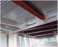
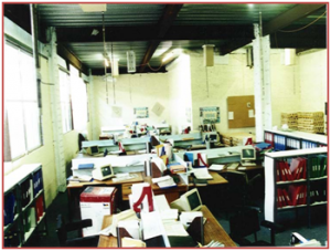
Unprotected steel beams at Plantation Place South, London.
(Image courtesy of Arup Fire)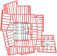
The floor plate at the Shard, London. Beams outlined in red are protected; the remainder are unprotected.
(Image courtesy of WSP Fire)


[top]Case studies


[top]References
- ↑ 1.0 1.1 Guide to the advanced fire safety engineering of structures. Institution of Structural Engineers, 2007
- ↑ 2.0 2.1 BS 7974: 2019. Application of fire safety engineering principles to the design of buildings. Code of practice. BSI
- ↑ PD 7974 - Application of fire safety engineering principles to the design of buildings (Parts 1 to 7). BSI
- ↑ 4.0 4.1 Approved Document B (Fire safety, Volume 2 – Buildings other than Dwellings), 2019 edition incorporating 2020 amendments – for use in England . Ministry of Housing, Communities & Local Government
- ↑ 5.0 5.1 5.2 BS EN 1991-1-2: 2002, Eurocode 1. Actions on Structures. General actions. Actions on structures exposed to fire. BSI
- ↑ 6.0 6.1 BS EN 1993-1-2. 2005, Eurocode 3. Design of steel structures. General rules. Structural fire design. BSI
- ↑ 7.0 7.1 BS 5950-8: 2003, Structural use of steelwork in buildings. Code of practice for fire resistant design. BSI
- ↑ NA to BS EN 1991-1-2: 2002, UK National Annex to Eurocode 1. Actions on Structures. General actions. Actions on structures exposed to fire. BSI
- ↑ PD 6688-1-2: 2007, Background paper to the UK National Annex to BS EN 1991-1-2. BSI
- ↑ 10.0 10.1 Building standards technical handbook: 2022 – Non-domestic, Section 2 – Fire, The Scottish Government
- ↑ Technical Booklet E, Fire safety, Building Regulations (Northern Ireland) 2012, Department of Finance and Personnel of the Northern Ireland Government, 2012
- ↑ 12.0 12.1 BRE Digest 462. Steel Structures supporting composite floor slabs: design for fire. Building Research Establishment
- ↑ BS EN 1994-1-2: 2005+A1:2014, Eurocode 4. Design of composite steel and concrete structures. General rules. Structural fire design. BSI
[top]Resources
- SCI P113 Structural fire engineering: Investigation of Broadgate Phase 8 fire
- Steel construction - Fire Protection supplement, 2013
[top]See also
- Design using structural fire standards
- Fire protecting structural steelwork
- Fire testing
- Sprinklers in UK fire codes
- Structural fire resistance requirements