


Thames Tower, Reading
Article in NSC March 2016

Tower tops out with steel
A 1970s concrete office block is being given a new lease of life with enlarged floorplates and four extra levels, all with the aid of steel construction.
By Martin Cooper
What to do with 40 or 50-year old tower blocks when their usefulness is seemingly over is a problem many towns and cities throughout the UK are increasingly having to deal with. Do you demolish the structure and start afresh by constructing a new building? Or do you refurbish the existing tower?
The latter has become the most popular choice, as it is the more cost-effective method. With reduced demolition to contend with, the overall refurbishment programme can begin immediately and consequently it will be completed far more quickly.
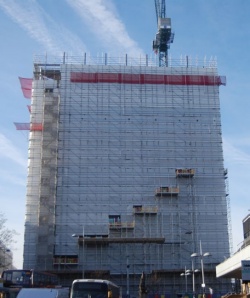
This was the challenge facing the clients of Thames Tower, a 12-storey concrete-framed 1970s office block that sits opposite Reading railway station and had been empty since 2010. Because of its prominent city centre position, the unoccupied tower had become a local eyesore and the project team was anxious to conclude a speedy construction programme.
Initially there were plans to demolish the building and replace it with a new 25-storey tower including new foundations. However this grandiose design was shelved and a more economical solution was put forward whereby four new steel-framed office floors would be added to the top of the existing tower, with no foundation works.

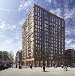
dn-a Director, Stuart McLarty comments: “Thames Tower originally had stumpy proportions, which contradicted its name as a tower. Adding 4 additional floors, squaring the corners and removing the concrete spandrels to allow for towering windows will create a more elegant, proportionate building. “Exposing the upper floors’ steel structure will highlight the contrast between the new steelwork and that of the old concrete Thames Tower, which is being reborn as a 21st Century workplace.”
Refurbishment work also includes stripping the building right back to its structural frame with the removal of its cladding, which will be replaced with a terracotta system to mirror redbrick buildings in the town.
“Steel is ideal for this kind of project as it is quick to erect and lightweight in comparison to other materials,” says Peter Brett Associates Director Fergal Kelly. “By strengthening some of the concrete columns we have added new floors to the top of the building, and crucially we have been able to reduce costs by re-using all existing foundations.”
As well as the four additional steel-framed floors, steel construction has also played a role in maximising and extending the existing floors of the tower. The structure’s original design had the perimeter columns protruding beyond the floorplates. For the new design, project steelwork contractor Shipley Structures has installed a series of new perimeter support beams that have been fitted and connected to the existing concrete columns.
These beams support new metal decking and a concrete topping, which brings the floors flush to the exterior face of the columns. “The beams have also provided the necessary support to allow the existing concrete perimeter upstands beams at level two up to 11 to be removed,” says Bowmer & Kirkland Senior Project Manager Bill Poole.

Altering the four corners of the building has further increased each of the tower’s existing commercial floorplates. Previously the corners featured a 45-degree chamfer, which has now been infilled to create a new perfectly square structure. This was achieved by Shipley Structures installing a new steel column in each of the building’s four corners. Two new connecting floor beams were then added at each floor which, in turn, support metal decking that forms the new floor space.
This work has increased the tower’s floor space from 13,600m2 to approximately 17,000m2 of offices and 740m2 of restaurant/café space.
“Before the new four-storeys of steelwork could be erected it was necessary for the existing concrete frame to be strengthened,” explains Shipley Structures Director Chris Murphy. “And the concrete frame also needed to be strengthened in order to support the tower crane that was required for the erection programme.”
A 500t-capacity mobile crane was required to install the site’s tower crane. However, due to the poor ground conditions surrounding the site, the chosen spot for this large crane had to be piled and strengthened prior to its arrival. “While these groundworks for the crane were being completed, we not only strengthened the concrete columns, but we also completed all of the perimeter steelwork for the existing tower,” says Mr Murphy. “As there was no tower crane we had to use hoists and lift most of the steel up through the cores.”

To strengthen the existing columns, flat 15mm-thick steel plates were attached to two faces of all internal columns from level six up to level ten. At levels nine and ten further strengthening plates were also fitted to the perimeter columns. At level 10 additional plates and stiffener brackets were fitted to three internal concrete columns located below the tower crane location. After all of these strengthening plates had been anchored into place they were then sealed and resin bonded to the existing concrete columns.
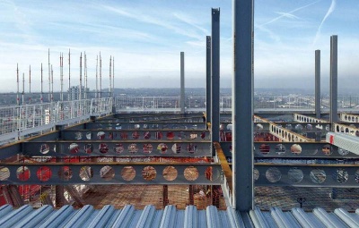
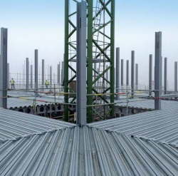
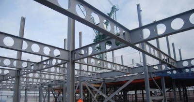
Once the strengthening works had been completed and the tower crane installed, Shipley began the erection of the new steel floors atop the tower. The new steelwork is bolted to the existing concrete columns, while in the corners the new frame connects to the steel columns previously erected by Shipley.
Predominantly based around a 6.3m × 5.8m internal grid to match the existing columns below, each new floor is formed with a series of Westok cellular beams that accommodate services and support metal decking. Westok’s London Regional Engineer, James Way, outlined why the cellular beams were beneficial, “The use of composite cellular beams has kept the steel weight to an absolute minimum, while allowing M&E services to be distributed within the structural depth. The weight savings have been of particular benefit on this project by minimizing the strengthening required to the existing structure.”
The structure has been built one floor at a time with the steel going up first and then the concrete being poured. Once this was completed and the concrete floor had cured, the works progressed to the next level with the team using the recently cast new floor as a surface for its mobile elevating work platforms. This working method was chosen because of the lack of space to store any materials on the tower’s roof or anywhere on the site. “There are vehicular restrictions around the site which meant we could only accept small loads of steel which had to be erected the day they arrived on site,” explains Mr Poole.
The steelwork for the new floors was completed in February and Thames Tower is due to be completed by early 2017.
Composite cellular beams
By SCI Associate Director David Brown

Long spans, light weight and services – combined with the demand for a low construction depth – leads to an integrated solution. Often, as at Thames Tower, the solution is a composite slab and a cellular beam. Composite cellular beams can be optimised to put steel where required – so the bottom half of the member is often a heavier section to accommodate the tension in what is effectively the bottom chord of a Vierendeel girder. The top half of the cellular beam may be smaller, since in composite construction the top half of the member is basically a separator between the tension in the bottom flange and the compression in the concrete slab.
Because the cellular beam acts like a Vierendeel girder, the web posts (the material remaining between the openings) and tee sections adjacent to openings can carry significant moments, especially towards the ends of the member. The structural checks are complex and best suited for software if an efficient solution is required. Where necessary, perhaps local to point loads or at the ends of members, cells can be filled in, or elongated openings may be strengthened with stiffeners. Good practice is to locate any necessary large openings away from the high shear zones.
In addition to extensive strength checks, the serviceability performance must be assessed, as this is obviously influenced by the openings in the beam. The additional deflection due to the openings in a cellular beam is typically 12 to 15% of that of an unperforated beam of the same depth. Fire protection is often provided by intumescent coatings; the coating thickness depends on the specific coating product and the beam geometry and load.
Although the design of cellular beams may appear complex, comprehensive design guidance is available. P355 covers the design of composite beams with web openings in accordance with the Eurocodes and UK National Annexes. Looking to the future, a specific Eurocode part is planned, covering the design of cellular beams although this is unlikely to be published before 2020.
Successful integrated solutions demand a co-ordinated design between the structural designer and the services engineer – neither process should be carried out in isolation. A very helpful overview of integrated solutions, including examples of good (and not so good) practice is given in the Co-construct guide IEP2 referenced below.
Resources:
- IEP2 Service Co-ordination with Structural beams . Guidance for a Defect-free Interface, BSRIA, SCI, 2003
- SCI P355, Design of Composite Beams with Large Web Openings, 2011
- Fire protection for structural steel in buildings (5th ed). The Association for Specialist Fire Protection
Links:
| Architect | dn-a architecture |
| Structural Engineer | Peter Brett Associates |
| Steelwork Contractor | Shipley Structures |
| Main Contractor | Bowmer & Kirkland |
| Main Client | Landid Property, Brockton Capital |