


Bracing systems
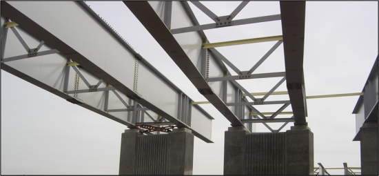
A bracing system is a secondary but essential part of a bridge structure. A bracing system serves to stabilize the main girders during construction, to contribute to the distribution of load effects and to provide restraint to compression flanges or chords where they would otherwise be free to buckle laterally. This article provides guidance on the design of bracing systems; additional guidance is available in Guidance Note 1.03 and Section 8.2 of SCI P356.

[top]Typical bracing systems
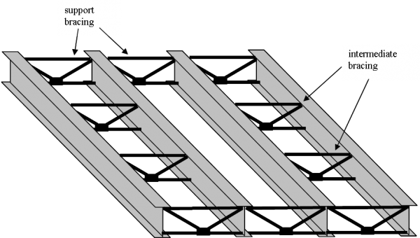
The figure below illustrates the general arrangement of a typical torsional bracing system for a multi-girder deck. The intermediate bracing can be triangulated as shown or a stiff beam with moment-resisting connections to the main girders. There are alternative bracing types for multi-girder decks, and these are discussed later.

[top]What does bracing do?
Bracing provides one or more of the following functions:
[top]Control of buckling of the main beams
The most common reason for providing bracing on a steel-concrete composite bridge is for the control of buckling in the main beams during construction. In composite bridges, the weight of wet concrete imposes significant bending of the bare steel beams and the compression flange needs to be restrained against buckling (in the direction of the minor axis). When completed, the concrete deck provides lateral restraint to the top flanges along the full length of the bridge and then the only portions of the beams that tend to buckle are the bottom flanges in the hogging regions adjacent to intermediate supports.
In an unrestrained beam, the compression flanges of the main beams tend to buckle horizontally, causing the beam to twist – so called lateral torsional buckling. This can be resisted by bracing that provides either direct lateral restraint to the compression flanges or torsional restraint to the whole beam.
A small tonnage of steel bracing can be used to provide huge increases in the bending resistance of the main beams.
[top]Load distribution
Since bracing connects beams, it can be used to distribute the vertical bending effects between the main beams, and to ensure that lateral effects such as wind loading and collision loading are shared between all the beams. This sharing is particularly important at lines of support, where the effects of the lateral loads are often resisted at one fixed or guided bearing (depending on the chosen articulation system).
In steel composite bridges during the "steel only" condition during construction, the main beams are particularly susceptible to wind loading. Bracing can be used to share loading between the beams so that the windward beam is not carrying the entire wind load.
In bridges curved in plan, bracing can provide the ‘radial’ component of force that is consequence of the changing direction of the curved flange. The effective couple of the forces at tension and compression flanges is resisted by additional vertical bending effects in the connected beams.
Bridges over highways or waterways may need to be designed for collision loads on the soffit. Over highways a soffit collision loading applies when the clearance is less than 5.7m (see the accidental actions in EN 1991-1-7[1], and its UK National Annex[2]). It is unlikely that a single main girder can resist the substantial loads without a bracing system to transfer forces to the remainder of the structure.
Load transfer may not always be desirable. The existence of bracing can affect the load distribution in a structure and the bracing itself can attract significant forces, particularly when a bridge deck is not equally loaded across its width. Bracing is usually much less substantial than the main girders and care is needed to ensure the bracing is not overloaded, and is not vulnerable to fatigue effects.
[top]Dimensional control
Partly as a result of deviation from exact geometry (within the usual tolerances) and partly as a result of unequal loading, the horizontal distances between the flanges of adjacent girders will vary, if not constrained. Such variation can cause problems during construction, particularly if permanent formwork is used, because this may result in an unacceptable reduction in the length of the formwork sitting on the beam flanges. Control bracing, often just one or two single angles, can be introduced to tie the beams together and thus limit the deviation.
It is also good practice to locate bracing systems close to one side of main beam site splice positions, for dimensional control (but the bracing should not be so close as to conflict with splice plates).
[top]Bracing types
Bracing can be classified into three types:
[top]Plan bracing


Plan bracing is perhaps the most obvious way to prevent lateral buckling of a compression flange. This is because plan bracing provides lateral restraint, i.e. it stops the compression flanges of beams from moving sideways.
Plan bracing takes the form of diagonal members, usually angle sections, connecting the compression flanges of the main beams, to form a truss when viewed in plan. This makes a structure that is very stiff in response to lateral movement. With lateral movement of the compression flanges thus resisted, the half wave length for buckling is reduced to the length between bracings.
Most plan bracing will be at top flange level. For steel composite bridges, this allows plan bracing to be cast within the deck slab, so it does not need to be painted and the underside of the bridge will have a clean, bracing-free appearance. However, where there are hogging moments in the main girders, there may need to be bracing on the bottom flange.
Plan bracing is not common in modern steel composite bridges. The main reason it is not used is because the plan bracing above the top flange conflicts with deck permanent formwork. It is, however, possible to position the plan bracing below the deck slab.
If plan bracing is not cast within the deck and is going to remain in the structure on completion, the performance of the bracing in service needs to be verified. Because the bracing is spanning partly in the longitudinal direction, longitudinal stresses will be induced in the bracing. Stresses can be determined by calculating the global displacements of the structure and imposing them on the bracing, or by adding the bracing to a comprehensive 3D structural model. No checks are needed for bracing within the deck slab, because the extra stiffness of the steel will be insignificant and concrete restrains the bracing against buckling.
Plan bracing can be used to form a "virtual box" girder. This is an alternative to the box girder which avoids the health and safety risks associated with the confined space interiors of box girders . The virtual box uses the deck slab or deck plate and plan bracing between the bottom flanges of two adjacent I girders to form a shape with torsional stiffness which can be used instead of a box girder.
[top]Torsional bracing
Torsional bracing takes the form of a plane of bracing between a pair of beams. The principal advantage of this type of bracing is that a pair of beams is a stable unit. Beams can be braced in pairs in the fabrication shop prior to transportation to site, which means that pairs can be craned into place very quickly with the minimum of site connections.
The bracing can take the form of a truss spanning laterally between the top and bottom flanges of the beams or can be a channel or I girder connecting the webs. In the case of ladder deck bridges, the bracing is provided by the transverse beams.

Torsional bracing systems

Structural action of torsional bracing


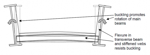
The bracing does not provide any lateral restraint to the compression flange, as one beam will simply use the bracing to push the other beam sideways. However the stiffness of the bracing will mean that both beams have to twist as a single unit, meaning that one beam is pushed up and one beam is pushed down, and their resistance to being pushed up and down is what provides resistance to buckling. For long transverse beams there is the possibility that the beams can twist in opposite directions, in which case the buckling mode is the same as that for U-frame action.
The effect of torsional bracing is to increase the elastic critical moment for each beam, although it will not increase it to the value for buckling over a half wave length equal to the spacing of the bracing. It is not ‘fully effective’ in the way that plan bracing is.
Torsional bracing is usually left in place permanently even if it is only needed for the temporary condition. If beams are only braced in pairs, the bracing does not have much effect on global load distribution, although checks need to be made that it is not overloaded by traffic loads. This can be by done by determining the global displacements of the structure and imposing them on the bracing, or by adding the bracing to a comprehensive 3D structural model.
Other advantages of this type of bracing over plan bracing are that it is located below the deck slab and therefore does not interfere with the construction of the concrete deck, and it can serve to distribute collision and wind loads more effectively.
[top]U frame bracing

Where compression flanges are remote from a direct lateral restraint, such as a deck, and are restrained laterally by flexible frames comprising a transverse beam in a deck and stiffened webs of the main beam, this is said to be a U frame, and the restraint is given by U frame action. The stiffness of the frame is what provides resistance to buckling.
U frame action is generally used to resist buckling in half-through girders, as is often the case in railway bridges. (Half-through girders are not often used for highway bridges because of the risk of collapse due to traffic collision with the main girders.)
In hogging zones of composite slab-on-beam bridges, U frame action may be used to restrain beams in the completed condition. This is particularly the case with ladder decks.
U frame action can only occur if there is a deck at or near tension flange level. The deck plate or slab will be very stiff in plan and will effectively prevent any lateral movement of the tension flanges. If this deck is not present, the frame will be a torsional restraint.
Guidance on determining the buckling resistance of a U frame bridge is given in a separate article on Design for half-through construction
[top]Design of bracing systems
There are three stages in the design of bracing:
- Identify suitable intermediate bracing positions (and their stiffness) for the adequacy of the main beams
- Design the intermediate bracing
- Design the support bracing.
[top]Making the main beams work

To calculate the buckling resistance of the beams, one method is to carry out an elastic critical buckling analysis. This will model the beams, usually representing each beam with fine meshes of finite elements representing the flanges and the web with 3-D grillages representing the bracing. This model is then analysed to determine the critical bending moment Mcr at which the main beam buckles. The result of this analysis can be used to determine the design bending resistance using EN 1993-2[3] clauses 6.3.2.2(1) and 6.3.2.1(3). The advantage of this method is that it can be applied to any situation and will give the optimum result for the strength of the beam. However, to suit most common situations a number of approximate methods are available which avoid the need for sophisticated analysis.
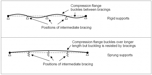
There are several simplified methods of determining the design bending resistance of main beams with bracing which use the analogy of a beam on springs. If the bracing is stiff enough the springs can be taken as rigid, and deflections from lateral or lateral torsional buckling can only occur between bracing positions. If the bracing is not stiff enough there could be deflections at the positions of bracing and the main beams will have lower bending resistance as a result.
To use these simplified methods it is necessary to calculate the spring stiffness of equivalent sprung supports. Sometimes it will be possible to show that the spring stiffness is so high that the supports can be taken as rigid.
[top]Design of plan bracing
Since plan bracing is provided to restrain the beams in the wet concrete condition, the calculations will be done for the bare steel structure.
The method of PD 6695-2[4] clause 5 applies to the case of rigid lateral restraints. The method is to calculate the non-dimensional slenderness λLT from which the design bending resistance can be determined using EN 1993-2[3] clauses 6.3.2.2(1) and 6.3.2.1(3). To see if the restraints can be assumed to be rigid, the requirement given in PD 6695-2[4] clause 5.3 may be used. This requires determination of the stiffness of the plan bracing system.
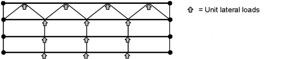
The stiffness of the plan bracing system is the stiffness of the whole structure. The suggested method is to use a 2-D structural model, representing the bridge steelwork in plan, and applying unit loads to all bracing positions, acting in the same direction, so as to give the worst case lateral deflection. If the plan bracing is only on the top flange, then in the model take the second moment of area as that of the compression flange only, bending laterally.
If the bracing system is not found to be rigid, there is no other simplified method available, and unless the design is changed to make the bracing stiffer, an elastic critical buckling analysis will be the only way to determine the design bending resistance.

[top]Design of torsional bracing
Torsional bracing is usually provided to restrain the beams in the wet concrete condition, so the calculations will be done for the bare steel structure.
The method of PD 6695-2[4] clause 8 applies to the case of torsional restraints. The method is to calculate the non-dimensional slenderness λLT from which the design bending resistance can be determined using EN 1993-2[3] clauses 6.3.2.2(1) and 6.3.2.1(3). The method introduces the concept of the half wavelength of buckling. As explained in PD 6695-2[4] clause 8.3 this could be the full span or some fraction of the span, but in most cases the half wavelength will equal the span.
A number of parameters need to be calculated using this method, starting with θR. A formula for determining one element of θR is given in PD 6695-2[4] clause 8, note 4. However θR can be determined relatively easily using a grillage model, representing the bridge steelwork, and applying several load cases as shown in the figure below.
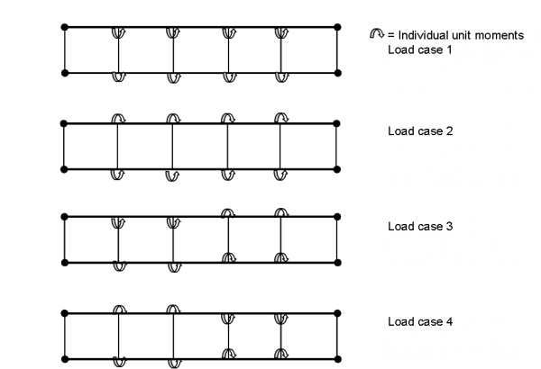

In each of the cases above, a moment is applied to each end of each torsional bracing, representing a unit force at the level of the top and bottom flanges. The moments are applied in different ways to reflect the different modes of buckling and the different half wavelengths of buckling that could occur. The above set is normally sufficient to cover all cases, but if either of the last two cases leads to a lower buckling resistance than the first two, it may be necessary to go on to consider the half wavelength of buckling equal to a third of the span, or a quarter etc. The outcome of these analyses will be to directly give θR. This result is combined with a number of section properties to eventually give the non-dimensional slenderness.
[top]Design of U frame bracing


U frame bracing is usually provided to restrain the beams in the completed condition, so the calculations will be done for the completed structure, not the bare steel structure.
The method of PD PD 6695-2[4] clause 9 applies to the case of U frame restraints and is based on the method given in EN 1993-2[3] clause 6.3.4.2. The stiffness of a U frame to lateral loading is referenced by the notes in EN 1993-2[3] clause 6.3.4.2 (2) and a formula is given in the second row of EN 1993-2[3] Table D.3. This formula can be derived quite easily from first principles as the deflection caused by a unit force applied at the top of each flange. However the formula given does not account for the flexibility of the joint itself, which will reduce the stiffness value and hence reduces the effectiveness of the restraint. Values for the flexibility are given in PD 6695-2[4] clause 9. Alternatively, a plane frame model of the cross section could be used to determine the stiffness of a U frame directly.
Using the stiffness calculate the limiting stiffness based on NE for the compression flange of each main beam. For this exercise take I to be second moment of area of the compression flange only bending laterally. Note that NE is the classic Euler buckling value (not to be confused with NEd which would be the design value of applied axial force) and is determined as if no restraint was provided. This value is then increased by the factor m which reflects the restraint offered by the U frames to give Ncrit which can then be used to determine the non-dimensional slenderness λLT from which the design bending resistance can be determined using EN 1993-2[3] clauses 6.3.2.2(1) and 6.3.2.1(3).
[top]Design of intermediate bracing
For the design of the bracing for strength, including connection strengths, the design forces need to be determined. The lateral forces can be determined using equation 6.11 in EN 1993-2[3] clause 6.3.4.2 (5) for plan bracing or the equations in PD 6695-2[4] clause 11 for torsional bracing and for U frames.
Add to this the direct forces on the bracing caused by lateral loads, for example by wind loading. If plane frame or grillage models have been used to determine the bracing stiffnesses they could also be loaded with wind load on the windward face to determine the distribution of forces from wind loading.
Bracing which remains in the structure permanently will also be affected by traffic loads and other variable actions, even if it is only required for temporary loads. To determine the effect from live loads two options are available. The easiest option is to extract the worst case distortions from the global grillage analysis and impose these results onto a plane frame local model of the intermediate bracing. However this is very conservative and it may be difficult to achieve a satisfactory design using this method. Alternatively, the actual bracing can be input into a comprehensive 3-D model of the structure. The latter method has the advantage that the loading on the bracing will be less than for the first method, the disadvantage is that a 3-D model takes longer to set up.
When designing the bracing members, do not forget that bracing members are generally slender and members that are subject to compression should be checked for buckling resistance.
[top]Design of support bracing
Support bracing has a different set of loads to resist. These are forces due to non-verticality of webs at the support, due to distortion introduced at skew supports, due to eccentricity of bearing reactions, and due to imperfection in alignment of compression flanges of the main girders.
The method of PD 6695-2[4] clause 10 can be used to determine all four of the above effects. The equations are used to determine a force FS. The most complicated part of the force FS4 is only applicable to skew supports. These forces are applied at the level of beam flanges to produce a torque. The forces are applied to a maximum of two beams, so for the case of a multi-girder bridge a variety of load cases may need to be considered.


The above figure indicates that the support bracing should be designed for the wet concrete condition. This is often critical, but the design should also consider the finished condition. In the finished structure the loads will be greater but the loads will be shared between the concrete deck and the steel bracing, so this condition may be less critical.
[top]Bracing detailing
[top]Choice of bracing
There are many types of bracing arrangement possible. As noted previously the general preference is for torsional bracing rather than lateral bracing.
For torsional bracing in multi-girder bridges, the K type bracing is usually preferred, rather than X bracing for tall main beams, but if main girders are shallow, relative to spacing, channel bracing would be better.
For ladder deck bridges, the bracing will be formed by transverse beams. A constant depth transverse beam is preferred, and if possible knee braces should be avoided.
[top]Dealing with skew
In skew bridges it is best to keep intermediate bracing normal to the main beams.
Support bracing in bridges with up to 20° skew can follow the lines of supports, i.e. being skew to the main beams. However if skew exceeds this value it is best to keep support bracing normal to the main beams and double up the support bracing as shown below.


More detailed guidance on arrangement of bracing is given in a separate article on skew bridges .
[top]Temporary or permanent bracing?
Most bracing is required only for the "wet concrete" construction condition. Once the concrete has hardened, the bracing is redundant. Bracing may even be a nuisance in the finished condition because it can attract large effects due to traffic loads and it can be difficult to make the bracing work. The question is therefore why not remove the bracing?
In general it is considered best to leave bracing in place. Although the weight of bracing is not much as a proportion of the overall tonnage, it is likely to be too heavy for manual handling and it can be quite difficult to manoeuvre the bracing out from under a completed bridge deck. The bracing may have taken up load and it may not be easy to remove bolts. Also leaving the bracing in place means that should the bridge need to be demolished in the future, the bracing could be used to stabilise the steelwork while the deck is broken out.
[top]Bracing connections
Bracing is almost always connected with bolts rather than welds. This allows the bracing to be easily assembled on site although in many cases beams are delivered to site already braced in pairs ready for lifting. Slip resistant connections are normally used. Guidance on slip resistant connections generally is given in a separate article on connections for bridge steelwork, and Guidance Note 2.03 specifically covers bracing and cross girder connections.
[top]References
- ↑ BS EN 1991-1-7:2006+A1:2014, Eurocode 1. Actions on structures. General actions. Accidental actions, BSI
- ↑ NA+A1:2014 to BS EN 1991-1-7:2006+A1:2014, UK National Annex to Eurocode 1. Actions on structures. General actions. Accidental actions, BSI
- ↑ 3.0 3.1 3.2 3.3 3.4 3.5 3.6 3.7 BS EN 1993-2:2006, Eurocode 3. Design of steel structures. Steel bridges, BSI
- ↑ 4.0 4.1 4.2 4.3 4.4 4.5 4.6 4.7 4.8 PD 6695-2:2008+A1:2012 Recommendations for the design of bridges to BS EN 1993, BSI
[top]Resources
- Iles, D.C. (2010) Composite highway bridge design. (P356 including corrigendum, 2014). SCI
- Hendy, C.R.; Iles, D.C. (2015) Steel Bridge Group: Guidance Notes on best practice in steel bridge construction (6th Issue). (P185). SCI
[top]See also
- Multi-girder composite bridges
- Ladder deck composite bridges
- Integral bridges
- Half-through bridges
- Box girder bridges
- Bridges - initial design
- Modelling and analysis of beam bridges
- Design of beams in composite bridges
- Fatigue design of bridges
- Stiffeners
- Connections in bridges
- Bridge articulation and bearing specification
- Plan curvature in bridges
- Skew bridges
- Design for steel bridge construction