


Bridges
Steel is widely used around the world for the construction of bridges from the very large to the very small. It is a versatile and effective material that provides efficient and sustainable solutions. Steel has long been recognised as the economic option for a range of bridges. It dominates the markets for long span bridges, railway bridges, footbridges, and medium span highway bridges. It is now increasingly the choice for shorter span highway structures as well. Society gains in many ways from the benefits delivered by steel bridge solutions. Landmark steel bridges embody good design, they are fast to build, and have stimulated the regeneration of many former industrial, dock and canalside areas.
Steel bridges are an essential feature of a country’s infrastructure and landscape. Few man-made structures combine the technical with the aesthetics in such an evocative way. Look closely at the next ‘landmark’ bridge you see; the chances are that it is made of steel.


[top]Attributes
Main Article: Sustainable steel bridges
Modern steel bridges taking advantage of the latest advances in automated fabrication and construction techniques are able to provide economic solutions to the demands of safety, rapid construction, aesthetics, shallow construction depth, minimal maintenance and flexibility in future use. Steel also scores well on all the sustainability measures, and offers a broad range of benefits addressing the economic, environmental, and social priorities of the ‘triple bottom line’ of sustainability.

(Image courtesy of Mabey Bridge Ltd.)
- Economic priorities
- Environmental priorities
- Social priorities

The high strength-to-weight ratio of steel minimises the structural weight of superstructures and thus minimises the substructure costs, which is particularly beneficial in poor ground conditions. Minimum self-weight is also an important factor in the cost of transporting and handling components. Use of steel facilitates shallow construction depths, which overcomes problems with headroom and flood clearances, and minimises the length and cost of approach embankments.
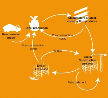
Steel is the most recycled construction material and choosing it for bridges represents a sustainable management of natural resources. When a steel bridge reaches the end of its useful life, the girders can be cut into manageable sizes to facilitate demolition, and returned to steelworks for recycling. Some 99% of structural steel either finds its way back into the steelmaking process where it is used to create new steel products or is reused. There is no degradation in the performance of recycled steel. Alternatively, component parts of steel bridges can be reused in other structures; entire bridges have been relocated and bridges can be designed with ease of future relocation in mind.
Steel has broad architectural possibilities. Steel bridges can be made to look light or reassuringly solid, and can be sculptured to any shape or form. The high surface quality of steel creates clean sharp lines and allows attention to detail. Modern fabrication methods can easily provide curvature in plan and elevation. The painting of steelwork introduces colour and contrast, and repainting can change or refresh the appearance of the bridge.
[top]Forms of construction
Main articles: Multi-girder composite bridges, Ladder deck composite bridges, Integral bridges, Half-through bridges, Box girder bridges, and Tied-arch bridges
Steel is a most versatile and effective material for bridge construction, able to carry loads in tension, compression and shear. Structural steelwork is used in the superstructures of bridges from the smallest to the greatest. There is a wide variety of structural forms available to the designer but each essentially falls into one of four groups; beam bridges, arch bridges, cable-stayed bridges and suspension bridges.
[top]Beam bridges
A beam and slab, or composite bridge is one where a reinforced concrete deck slab sits on top of steel I-beams, and acts compositely with them in bending. There are two principal forms of this beam and slab construction; multi-girder construction and ladder deck construction. Between them, they account for the majority of medium span highway bridges currently being built in the UK, and are suitable for spans ranging from 13m up to 100m. The choice between the two forms depends on economic considerations and site-specific factors such as form of intermediate supports and access for construction.
- Cross sections

Cross section of a multi-girder highway bridge
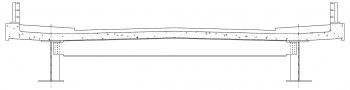
Cross section of a ladder deck bridge


- Examples
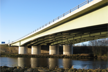
Twin multi-girder bridge structures, showing bracing locations
Lagentium Viaduct, Castleford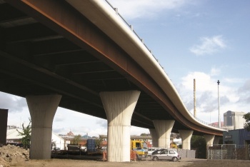
A twin ladder deck bridge
Hunslett Viaduct, Leeds


Increasingly, such composite bridges are adopting ‘integral construction’, where the deck is rigidly connected to the abutments. This eliminates the need for expansion joints and bearings, which minimises future maintenance requirements.
In some situations, notably for railway bridges, the depth between the trafficked surface (or rails) and the underside of the bridge is severely constrained and there is little depth available for the structure. In these circumstances, ‘half-through’ construction is used.


[top]Box girder bridges
Box girders comprise two webs that are joined top and bottom by a common flange creating a closed cell that offers very good torsional stiffness, which may be required on highly curved bridges. In beam and slab bridges, box girders are an alternative to plate girders at the upper end of the span range, where they offer a lower steel weight, although this has to be balanced against increased fabrication costs. Such composite box girder decks may take the form of multiple closed steel boxes, with the deck slab over the top, or an open top trapezoidal box, closed by the deck slab.
Longer spans of 100 to 200m typically use either a single box or a pair of boxes with crossbeams. For such long spans and for bridges such as lifting bridges, where minimising structural weight is very important, an all-steel orthotropic deck may be used instead of a reinforced concrete slab. Above about 200m, box girders are likely to be part of a cable-stayed bridge or a suspension bridge, where they are specially shaped for optimum aerodynamic performance.
- Box girder bridges
Variable depth trapezoidal closed top box girders
River Nene Viaduct, Peterborough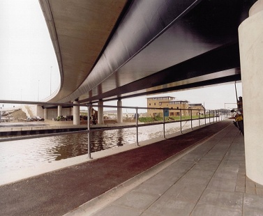
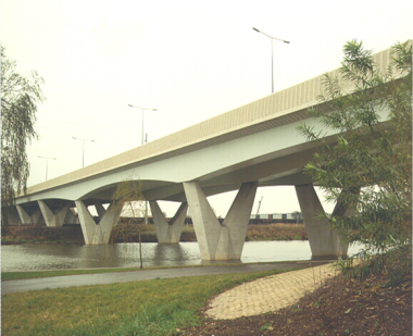
Open top box girders curved in plan
Fossdyke Bridge, Lincoln


[top]Truss bridges
A truss is a triangulated framework of individual elements or members which act primarily in tension or compression. Trusses have been used in a similar way to beams in composite decks (Oresund Approach Spans), as arches (Sydney Harbour Bridge), as cantilevers (Forth Rail Bridge) or as stiffening girders to suspension bridges (Forth Road Bridge).
Today, the truss girder form of construction usually proves expensive to fabricate because of the large amount of labour-intensive work in building up the members and making the connections, so they are seldom used for ordinary highway bridges. However, for through or half-through forms, truss bridges do offer a very stiff, lightweight solutions with minimum structural depth. Hence, they are widely used in the UK for footbridges, demountable bridges (Bailey bridges), gantries and longer span railway bridges (over 50m).
- Truss bridges
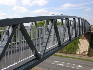
Half-through warren truss footbridge
(Image courtesy of Nusteel Structures Ltd.)
Through truss railway bridge
New Cross Gate Flyover, London


[top]Arch bridges
In the traditional form, a steel arch has a similar structural action to old masonry arch bridges. The arch springs from the foundations and exerts horizontal thrusts on them. The arch elements act primarily in compression. The deck may either be supported on struts, resting on arch below, or it may be suspended on hangers from the arch above.
A tied-arch or "bow string" arch is a particular development of the arch form. The horizontal thrusts from the arching action are resisted by tension members between the arch springings. Effectively the deck acts as a tension tie, and is supported by hangers from the arch above. This form is suited to the soft soils of riverbanks, where the ground cannot withstand the large horizontal thrusts from arching action.
In recent years, arches and tied-arches have become a little more common, partly because the use of an arch from which to hang the deck allows the construction depth of a suspended deck to be kept shallow, even at longer spans, and partly because arches make a clear architectural statement. Arches are sometimes skew to the line of the deck and sometimes the arch planes are inclined for dramatic visual effect.
- Arch bridges
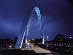
Arch skew to the line of the deck
Hulme Arch, Manchester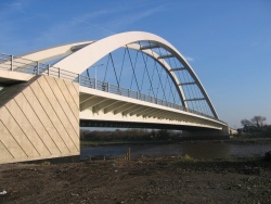
Tied-arch bridge
River Usk Crossing, Newport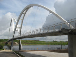
Tied-arch bridge
Infinity footbridge, Stockton


[top]Cable-stayed bridges

In this form of bridge, the main girders are supported at intervals along their length by inclined tension members (stays) connected to a high mast or pylon. There may be either a single plane of stays down the centre of the bridge, or two planes; one on each side of the bridge. The towers act in compression and can have a variety of forms (A-frame, H-frame or columns). The deck girders sustain compression forces as well as bending forces.
Recent developments in the modelling and analysis of dynamic behaviour and the use of sophisticated damping against oscillation have extended the realm of the cable-stayed bridge to spans in excess of 1000m, which had previously been the almost exclusive domain of suspension bridges. The visual appearance of stayed structures can be very effective, even dramatic. They are frequently considered appealing or eye-catching. On a more modest scale, cable-stayed construction is sometimes used for footbridges, to give support and stiffness to an otherwise very light structure.
Examples of cable-stayed bridges include:
[top]Suspension bridges
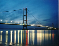

A suspension bridge is fundamentally simple in action: two cables are suspended between two supports (‘towers’ or ‘pylons’), hanging in a shallow curve, and a deck is supported from the two cables by a series of hangers along their length. The cables and hangers are in simple tension and the deck spans transversely and longitudinally between the hangers. In most cases the cables are anchored at ground level, either side of the main towers; often the side spans are hung from these portions of the cables.
In addition to its action in carrying traffic, the deck acts as a stiffening girder running the length of each span. The stiffening girder spreads concentrated loads and provides stiffness against oscillation; such stiffness is needed against both bending and twisting actions.
Because of their fundamental simplicity and economy of structural action, suspension bridges have been used for the longest bridge spans. The graceful curve of the suspension cable combined with the strong line of the deck and stiffening girder generally give a very pleasing appearance. The combination of grace and grandeur in such situations leads to the acknowledged view that many of the world’s most exciting bridges are suspension bridges.
One recent example of a smaller suspension bridge is Peace Bridge, Derry-Londonderry
[top]Materials
Main articles: Material selection and product specification and Weathering steel

Structural steel is a high-quality material that is readily available worldwide in certified grades, in products of various shapes and sizes. Prefabrication of steelwork in controlled factory conditions leads to high quality work at minimum cost. The excellent quality control is achieved through a thorough testing regime at the steel mills and during the fabrication processes of cutting and drilling, assembly, welding, and protective treatment. The quality assurance that is attained should give confidence to all clients and engineers who specify steel for their bridge project.
Steel material is supplied in two product forms – ‘flat products’ (steel plate and strip) and ‘long products’ (rolled sections, either standard open sections such as beams, channels, angles, etc or hollow sections). For structural use in bridges these products are inevitably cut (to size and shape) and welded, one component to another. In the structure, the material is subject to tensile and compressive forces. Structural steel generally responds in a linear elastic manner, up to the ‘yield point’ and thereafter has a significant capacity for plastic straining before failure. All these aspects of steel material are utilised by the designer of a steel bridge.
The selection of an appropriate grade of steel for a bridge requires an awareness of the steel manufacturing process, an appreciation of the relevant product standards and an understanding of several issues including:
Steel derives its material properties from a combination of chemical composition, mechanical working and heat treatment. The yield strength is probably the most significant property that the designer will need to use or specify. The achievement of a suitable yield strength whilst maintaining other properties has been the driving force behind the development of modern steel making and rolling processes.


S355 steel is predominantly used in highway bridge applications, as it is readily available, and generally gives the optimum balance between stiffness and strength. S275 steel is often used on railway bridges, where stiffness rather than strength governs the design, or where fatigue is the critical design case. S420 and S460 steels can offer advantages where self-weight is critical or the designer needs to minimise plate thicknesses. However, the use of such steels confers no benefits in applications where fatigue, stiffness or the instability of very slender members is the overriding design consideration. These steels are also less readily available in the UK.
Other mechanical properties of particular importance to the bridge designer include ductility, toughness, weldability, and corrosion resistance.
All structural steels, with the exception of ‘weathering steel’, have a similar resistance to corrosion. In exposed conditions they need to be protected by a coating system. There are no special requirements of the steel material for ordinary coating systems, including both aluminium and zinc metal spray. However, if the steel is to be galvanized, then there is a need to control the alloy content (notably the Silicon content).
Weathering steel is a high strength low alloy steel that in suitable environments forms an adherent protective rust ‘patina’, to inhibit further corrosion. The corrosion rate is so low that bridges fabricated from unpainted weathering steel can achieve a 120 year design life with only nominal maintenance.
[top]Design
Main articles: Bridges - initial design, Modelling and analysis of beam bridges, Design of beams in composite bridges, Shear connection in composite bridge beams, Design for half-through construction, Design of steel footbridges, Fatigue design of bridges, Bracing systems, Stiffeners, Connections in bridges, Bridge articulation and bearing specification, Plan curvature in bridges, Skew bridges, and Specification of bridge steelwork

Designers of steel bridges are well supported with a wealth of guidance to assist them in designing the most economic solution for their clients. This extends from initial concept design, through detailed design verification and on to appropriate specification.
In the concept design stage, the designer takes the outline requirements of the alignment engineer (the road, rail or pedestrian layout, cross section and vertical profile) and derives a structural solution that suits the topography and restrictions of the site, whilst minimising both costs and risks. There may be little detailed calculation at this stage but there should be consultation with steelwork contractors and main contractors. Most bridge construction in the UK currently takes place under collaborative arrangements and thus access to steelwork contractors and main contractors should be readily available to the designer. In the absence of a collaborative arrangement, designers should at least discuss the options with a steelwork contractor at an early stage.
While minimising cost may be the most obvious consideration when embarking on the design of a steel bridge, the health and safety of all those concerned in the construction of the bridge and in its maintenance throughout its life is the responsibility of all those people making decisions about the procurement of the bridge. So, as well as aiming for a structurally efficient solution, designers should consider how the steelwork will be fabricated and erected, how the deck will be completed (i.e. design for construction), and how the bridge will be maintained. The chosen bridge erection scheme will clearly have a big influence on the type and location of any connections.
Preliminary sizing is part of the concept design, and is often based on crude estimations of load distribution, and resulting bending moments and shear forces. However, for steel composite highway bridges, preliminary design charts and an associated software tool are available to facilitate far more accurate initial girder sizes
Detailed design is effectively design verification to the Eurocodes, which is more of a checking process than original creative design. Modelling and analysis is carried out for the selected structural arrangement for the various loading conditions (including fatigue) taking full account of any curvature and skew. The adequacy of the main members (composite beams, half-through beams, and box girders etc.) is then checked in detail to ensure that they are adequate to carry the applied moments and forces. Details such as shear connection, stiffener sizes and bracing member sizes, etc, are chosen at this stage to suit the global actions of the main members.
The main output from the design process is often seen as a set of drawings, but designers should also recognise the importance of an appropriate specification. It is important that a project specification (and the accompanying drawings) should express clearly the particular requirements for a structure and, where standards allow options and alternatives, which additional requirements apply. Failure in clarity will lead to extra provisions for risk and extra costs in resolving queries. The project specification should also avoid over-specification, requiring unnecessary quality and excessively tight tolerances will lead to higher costs. The project specification should generally follow recognised industry standards, such as the Specification for Highway Works[1].
[top]Construction
Main article: Design for steel bridge construction

(Image courtesy of Mabey Bridge Ltd.)
Offsite prefabrication of steel components means that construction time on site, often in hostile environments, is minimised. The speed of bridge construction made possible by steel allows disruption to road and rail users to be kept to a minimum, if not eliminated, with significant positive knock-on effects for the UK economy. The relatively low weight of structural steel components permits the erection of large sections; in some circumstances complete bridges can be moved into position overnight. Speed of steel bridge construction also benefits main contractors even on ‘green field’ sites, as it allows them to establish and maintain access for haul roads.
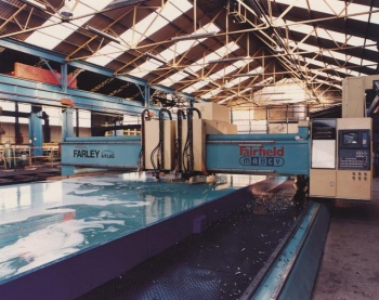
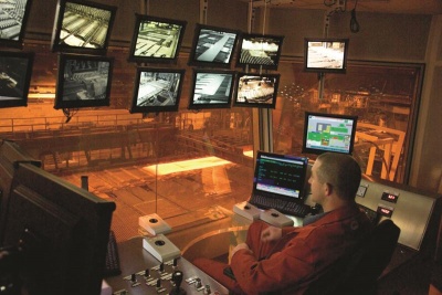
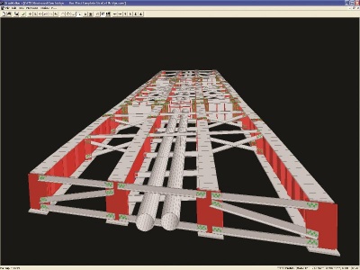
One of the key drivers behind the success of steel bridges in the UK since the 1980s has been the continuous investment by steelwork contractors in automated fabrication equipment for cutting and drilling, girder assembly and welding steel. Production efficiencies are further enhanced within modern factories by working on a number of projects in parallel to achieve profitable utilisation of the space, equipment and permanent workforce. The fabrication process begins with 3D modelling the bridge steelwork with CADCAM software, which creates a list of components (girder webs and flanges, stiffeners and bracing elements etc.) required for the structure and produces the programs for the automated fabrication equipment. The model is also used to locate and rectify conflicts and can even carry out a virtual trial erection. Once the steelwork has passed through the factory, it is usually then blast cleaned and painted prior to transportation to site.


(Image courtesy of Mabey Bridge Ltd.)
A wide range of construction methods and sequences are available for steel bridges. They can be lifted, piece-by-piece, by cranes or strand jacks; they can be launched by sliding or rolling from the abutment; or they can be slid or transported into position. In some instances a combination of erection methods are needed; these are called ‘Hybrid schemes’. Steel offers flexibility in terms of erection sequence and certainty in terms of the programme and, once erected, the steel girders provide platforms for subsequent deck construction operations.
The involvement of a steelwork contractor during the concept design and detailed design stage depends very much on the form of contract, but even with relatively ‘ordinary’ structures it is desirable to seek their advice at an early stage. The steelwork contractor can provide assistance with design for construction, i.e. the definition of the structural concept, steelwork detailing and planning the proposed erection scheme. This ensures that the costs associated with steelwork contract are minimised.
Videos of bridge construction:
1. Borough High Street Bridge, London being installed.
2. Mallard Bridge on White Rose Way, Doncaster being installed over the East Coast Main Line using one of the largest mobile cranes in the UK.
3. Leigh Road Bridge installation using specialist transporters in Slough.
[top]Durability
Main articles: Corrosion protection and Weathering steel
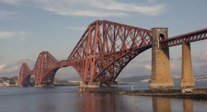

Steel bridges now have a proven life span extending to well over 100 years. A notable example is the imposing Forth Rail Bridge in Scotland, which was completed in 1890. The scale and size of this significant landmark was a major achievement in construction engineering, and the structure has stood the test of time.
Steel has a predictable fatigue life and the structural elements are visible and accessible. Any signs of deterioration are readily apparent, without the need for extensive investigations. Corrosion is a surface effect, which rarely compromises the structural integrity of a bridge, and any problems may be swiftly addressed by repainting the affected areas. Advances in coating technology and an industry commitment to the training of coating applicators mean that the latest protective systems are expected to last well beyond 30 years before requiring maintenance. Furthermore, the use of unpainted weathering steel, which requires almost no maintenance, is increasingly popular, as it is recognised as the ultimate low maintenance option for bridge construction.

(Image courtesy of AECOM)
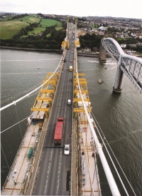
Steel bridges are readily adaptable to changes in road configuration and increased loading that would render other types of structure obsolete ahead of their original design lives. One notable example is the Tamar suspension bridge in Plymouth, which needed widening and strengthening due to increased traffic loads and volumes. The solution was to replace the concrete deck with a new lightweight steel one, and add steel cantilever sections. The result was that the widened 5-lane bridge was only 25 tonnes heavier than the old 3-lane structure, and was able to accommodate 44 tonne trucks.
Steel bridges also lend themselves to easy and rapid strengthening or repair in the event of accidents, with well proven techniques like heat straightening ensuring that damaged structures are soon back in use.
The fundamental requirements to fully realise the potential durability of a steel bridge include:
- An understanding of the corrosion process
- Good design and detailing
- Thorough surface preparation
- Use of high quality coatings
- Correct coating application
- Appropriate specifications
- Inspection and quality control

(Image courtesy of Mabey Bridge Ltd.)
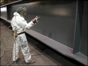
The majority of steel bridges in the UK are protected against corrosion by the use of paint coatings. Modern specifications usually comprise a sequential coating application of paints or alternatively paints applied over thermally sprayed metal coatings to form a ‘duplex’ coating system. The protective paint systems usually consist of primer, intermediate coat(s) and finish coats. Each coating ‘layer’ in any protective system has a specific function, and the different types are applied in a particular sequence of primer followed by intermediate/build coats in the shop, and finally the finish or top coat on site. Hot-dip galvanizing is an alternative durable coating that is sometimes used, although its use is generally limited to smaller bridges due to the nature of the application process.
[top]Case studies


[top]References
[top]Resources
- Hendy, C.R.; Iles, D.C. (2015) Steel Bridge Group: Guidance Notes on best practice in steel bridge construction (6th Issue). (P185). SCI
- Hendy, C.R.; Iles, D.C.; Palmer, I. (2017) Steel Bridge Group: Completion of Appendix 18/1. (P418). SCI
- Iles, D.C. (2004) Design guide for steel railway bridges (P318) SCI
- Iles, D.C. (2010) Composite highway bridge design. (P356 including corrigendum, 2014). SCI
- Iles, D.C. (2010) Composite highway bridge design: Worked examples. (P357 including corrigendum, 2014). SCI
- Iles, D.C. (2012) Design of composite highway bridges curved in plan. (P393). SCI
- Iles, D.C. (2012) Determining the buckling resistance of steel and composite bridge structures. (ED008). SCI
- Iles, D.C. (2015) Determining design displacements for bridge movement bearings. (P406). SCI
- Steel Bridges: A practical approach to design for efficient fabrication and construction, 2010, (Publication no. 51/10), BCSA,
- Guide to the Erection of Steel Bridges, 2005, (Publication no. 38/05), BCSA
- Carbon footprint tool for steel composite highway bridges
- Preliminary steel bridge design charts:
- Chart finder
- Spreadsheet tool
- User manual
- All three of which can be found on the BCSA web site
[top]See also
- Sustainable steel bridges
- Multi-girder composite bridges
- Ladder deck composite bridges
- Integral bridges
- Half-through bridges
- Box girder bridges
- Tied-arch bridges
- Material selection and product specification
- Weathering steel
- Bridges - initial design
- Modelling and analysis of beam bridges
- Design of beams in composite bridges
- Shear connection in composite bridge beams
- Design for half-through construction
- Design of steel footbridges
- Fatigue design of bridges
- Bracing systems
- Stiffeners
- Connections in bridges
- Bridge articulation and bearing specification
- Plan curvature in bridges
- Skew bridges
- Specification of bridge steelwork
- Design for steel bridge construction
- Corrosion protection
- Welding
- Preloaded bolting
- Accuracy of steel fabrication