


Bridges - initial design
The choice of bridge form is usually made at an early stage and one or more initial configurations with principal dimensions are selected for more detailed evaluation. This article discusses the factors influencing the choice of form and provides guidance on preliminary sizing of the structural members. It focuses on typical composite highway bridges of medium span.

[top]Determining factors
In order to develop a viable concept for a bridge crossing and to choose a preliminary configuration and dimensions, the designer must consider a number of inter-related factors:
- Constraints of the crossing site: e.g. highways, railway lines, rivers, canals or other water courses; deep or steep sided valleys; environmentally sensitive sites requiring minimal disturbance. Ground conditions can also be a constraint not just for the bridge foundations but the approach embankments as well.
- Service life. The bridge is normally designed for 120 years service life, but items such as a steelwork corrosion protection system, deck joints and bearings will need to be maintained or replaced during the service life of the structure. Concrete in substructure elements and deck slabs will also require maintenance.
- Costs of material and components. Steelwork is prefabricated in factory conditions but the costs of doing so depend on the components used (rolled sections or plates, for example) the complexity of the structure and the size of the elements. Concrete slabs can be cast in situ or formed partly from precast components.
- How the bridge can be assembled and completed on site. Is it a greenfield site?; is construction only possible in limited possessions?; what plant can be got to the site?
- Health and safety considerations, notably the CDM regulations[1]
- Appearance, notably the client’s aspirations.
[top]Structural form


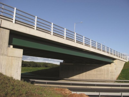
A34 Wolvercote Viaduct, Oxford
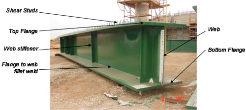
For medium span highway bridges built in the UK in recent years, by far the most common form has been the deck type steel-and-concrete composite bridge. With bridges of this type the structural steelwork system generally comprises fabricated 'I' section plate girders, and these support a concrete deck slab at top flange level. The discussion of considerations at the concept design stage relates principally to that type of bridge and also to other forms of steel bridge construction.
The forms of construction covered below are thus principally multi-girder decks and ladder decks although the general guidance will be equally applicable to deck type bridges utilising box girders (open and closed top boxes in place of 'I' girders) and to half-through bridges.
[top]Span length
The designer has to determine the span lengths and number of spans for the bridge from consideration of the alignment, the topography of the site, the physical dimensions of the obstacle (or obstacles, including services that may be too expensive to relocate) to be crossed, the required clearance envelopes, the available locations for the bridge abutments and intermediate piers (if more than one span), the appearance and any particular requirements that the client may impose. Whilst straight bridges crossing square are the ideal, bridge layouts may need to be skewed and/or curved. For highway bridges refer to CD 127[2] for cross-sections and headrooms.
Any pier within 4.5m of the edge of the carriageway has to be designed for impact loads (as given by the National Annex to BS EN 1991-1-7[3]) but abutments do not normally have to be considered.
Nowadays for single span bridges, except for the shortest spans, steel composite decks compete with prestressed concrete Y-beam decks and generally will prove more economical at the upper end of the Y-beam span range. For two or more spans continuous decks are the norm and steel composite decks, because of their superior buildability, should win over Y beam decks. When optimising span lengths in multi-span bridges, shorter spans (typically 25m to 30m) will be more economical. However where piers are costly (for example when very tall piers or deep piled foundations are needed), or the environmental sensitivity of the site requires minimal disturbance, longer spans with fewer foundations are likely to be more economical.
For bridges with three or more spans, the optimum length of the end span is usually from 0.7 to 0.85 of the adjacent internal span length. With very short end spans, uplift can occur at the abutments. Where more than one arrangement of spans could provide a viable crossing, the cost, buildability and appearance of the alternative options are evaluated to obtain the preferred solution. This evaluation will include the costs of the substructure and foundations.
[top]Example of options for a bridge over a dual carriageway road
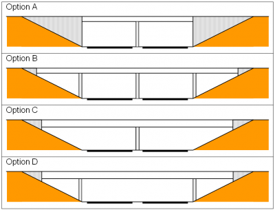

Arrangements A, B, C and D shown right are all possible layouts for crossing a dual carriageway. Arrangement A might be considered the best for a greenfield site as it provides the shortest spans and the shortest overall deck length. A high wall type abutment can be more expensive than an additional side span (B) or a longer span (C), particularly with integral construction. Where construction depth is at a premium B would be preferable to C. When crossing over an existing motorway or dual carriageway, it is often difficult to construct a pier between the carriageways because the works have to be carried out under traffic management, so arrangement D would be preferred.
[top]Integral construction
For highway bridges, integral construction must be considered and designers should follow the advice given in PD 6694-1[4]. Nowadays the Technical Approval Authorities expect bridge decks up to 60m in length and with skews (at the abutments) not exceeding 30° to be integral with the abutments unless there are valid reasons, such as potential mining subsidence, for them not to be so. Note that 60m is not a limit on maximum length for integral bridges, Highways England have accepted integral bridges with lengths greater than 100m.
An integral bridge is necessarily continuous over intermediate supports (there are to be no provisions for movement joints at these locations) but does not need to be integral with the columns or piers beneath. The girders can simply sit on ordinary bearings. Eliminating the bearings by casting in the main girders or steel crosshead girders does not bring major benefits and does increase complexity in construction; the tendency to attract moment may also develop potential fatigue problems.
Continuous spans will invariably be more economical in steel weight than simply supported spans of the same length. With non-integral construction provision of an abutment gallery is expensive and can impact on construction programme. Hence integral bridges will almost always be more economical than non-integral, especially when whole life costing is taken into account as user delay costs associated with deck joint maintenance/replacement are high.
[top]Steelwork system and deck slab
The most popular steelwork systems being used today for highway bridge construction are multi-girder decks and ladder decks. Which system is the more cost effective from the point of view of prefabrication and erection for a particular site will depend on the site specific determining factors, so there are no hard and fast rules to aid selection.
Whichever the system, the structural steelwork will usually be fabricated plate girders of 'I' section. However boxes may be used for appearance reasons (often a look-alike replacement has to be provided for an original design that was a prestressed concrete box), or where the deck is tightly curved in plan.
As ladder deck bridges have only two main girders, the question of structural redundancy might be raised in the choice of ladder deck configuration – if some accidental event were to damage one girder so severely that it could no longer carry even the dead loads, the bridge would collapse. There is no data on the likelihood of accidental events that could cause such damage, for either ladder deck or multi-girder decks, and it is therefore not possible to make any quantitative assessment of reliability for either type. The girder sections of ladder deck bridges are generally larger than those of multi-girder decks and they are also restrained at close spacing by the cross girders; designers therefore consider this configuration to be sufficiently robust.
The thickness of the composite concrete deck slab on deck type bridges typically will be 250mm. An in-situ slab of this thickness, cast either on timber formwork or permanent formwork, will span around 3.5m, hence girder spacing (main girders in multi-girder decks, cross girders in ladder deck systems) will typically be at 3.5m centres, or a little more as the slab spans between the flange outstands. Generally contractors like to use permanent formwork (Omnia planks are the market leader) rather than conventional timber formwork. Use of proprietary parapet cantilever formwork systems is now widespread for the deck slab cantilevers. Cantilever length is usually not more than half the girder spacing on multi-girder decks, typically 1.5m. The designer needs to consider how the steelwork system and deck slab are arranged geometrically to accommodate crossfall and superelevation, and whether to split dual carriageway underbridge decks down the middle. CD 377[5] has specific requirements for designing a divided structure with a longitudinal gap between the two bridge decks.
When determining the form of the substructure, particularly the type of pier, it should be borne in mind that it is preferable to put the bearings directly under the main girder. The tops of piers and columns should provide sufficient space for jacks to be inserted for bearing replacement, and additional jacking stiffeners should be provided in corresponding positions adjacent to the main bearing stiffeners. Ladder deck steelwork systems and multi-girder systems with integral crossheads reduce the number of intermediate support columns and bearings. However integral crossheads are expensive to fabricate and complicate erection, so their use should be avoided unless there are particular constraints due to limited space or appearance. When used considerable thought needs to be given as to how to detail the steelwork to accommodate the crossfall and the longitudinal gradient of the carriageway.
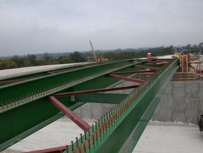
[top]Girder spacing and layout
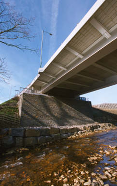

(Image courtesy of Rob Watkins)
Girder spacing is controlled by the spanning ability of the concrete deck slab. For a 250mm deck slab this leads to a maximum span for the slab of about 4m. This spacing is consistent with the maximum span of permanent formwork, typically about 3.8m. Deck slab cantilevers at the edge of the deck will control the position of the outer main girders. A cantilever of 1.5m is common and can work economically with a 250mm deck slab. With these primary dimensional constraints identified, the main steel grid can be defined to suit the particular geometry and dimensions of the bridge.
For a multi-girder bridge, an even number of main girders should be selected, such that the limits on cantilever length and girder spacing are observed, Longer cantilevers] can be achieved with care and may be preferable for aesthetics: the edge cantilever should ideally be similar to the depth of the outer girder.
For ladder decks, the spacing of the main girder is dictated by the chosen length of cantilever, with a maximum spacing of about 18m. Cross girders are generally spaced at between 3.5m and 3.8m but the spacing will need to be adjusted at the ends and intermediate supports of skew bridges. Steel cantilevers can be added to support longer cantilevers on ladder decks if required and can also be used to avoid cantilever falsework. They do, however, have cost implications.
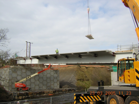

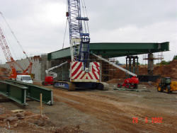
(Image courtesy of Costain)
[top]Initial size estimates for main girders
Previous experience will often be the first guide to selection of flange and web sizes for the main girders and cross girders. The selection can be refined using simple ‘rules of thumb’ or by the use of design charts and software.
In almost all cases, steel grade S355 (to BS EN 10025[6]) will offer the most economic solutions and bridge steelwork contractors have extensive experience of processes to fabricate steelwork of that grade.

[top]Simple rules for proportioning girders
The main girders can be proportioned according to the following rules of thumb, which are based upon a typical highway bridge of two or more spans carrying a single carriageway over a dual 2 or dual 3 lane highway. Large bridges will need to have their sizes adjusted upwards in a proportional manner, e.g. wide ladder decks will require proportionally wider and thicker flanges.
| Element | Proportioning | Comments |
|---|---|---|
| Girder Depth | Span/20 to Span/30 | For wide ladder decks and simply supported spans, ratios should be kept to 20. A higher ratio will likely result in a heavier steel weight. |
| Top flange width | Minimum width 350 mm | Minimum width to facilitate shear studs, splices and precast formwork. Minimum width can be applied to most single carriageway bridges with spans up to about 30 m. |
| Top flange thickness | In sagging zones: 21 mm for 350 mm minimum flange width. In hogging zones thickness increases significantly. |
This is based upon an 8:1 outstand ratio for EN1993-1-1[7] table 5.2 for grade 355 steel for a class 2 section. Preliminary analysis best to ascertain top flange thickness in hogging zones. |
| Bottom flange width | Typically approx. half the girder depth. | |
| Bottom flange thickness | Mid span sagging or hogging at supports. Ladder deck: 55 to 60 mm typical. |
This is the most difficult dimension to estimate without analysis. Flange thickness should be varied through the length of the girder to optimise design. |
| Webs | Minimum web = 15 mm in mid span zones, increasing to 20 mm or 25 mm at supports. Multi girder decks will probably work at 20 mm webs at supports. Ladder decks likely to need 25 mm webs. |
This is a practical minimum for robustness during construction. Webs should be assumed to be working near their maximum allowable stresses for efficiency: web stiffeners will enable. |
| Web to flange welds | Smaller girders: 6 mm at midspan. Up to 8 or 10 mm at supports. Larger spans, ladder decks: 8mm at midspan; up to 10 mm at supports. |
Weld sizes are expressed as either leg length or throat length; one run of weld laid down each side of the web. 6 mm (leg length) is a practical minimum weld size. |
| Shear Studs | Use 19mm diameter by 150 mm high studs. Typically rows of 3 at 300 mm centres at mid span increasing to rows of 3 or 4 at 150 mm centres at supports. |
The spacing needs to be coordinated with the detailing of the transverse reinforcement. |
Plate thicknesses may be chosen to the nearest millimetre (or perhaps rounded up to the nearest 5mm at this stage, leaving a more precise selection to be made at the detailed design stage). Plate widths would normally be refined to the nearest 50mm.
[top]Design charts and software
An early estimation of the sizes of steel sections in a medium-span composite highway bridge can be made by using Preliminary steel bridge design charts.
The design charts cover both ladder deck and multi-girder forms of construction and account for the differences between inner and outer girders in multi-girder bridges. They also cover both elastic and plastic design of sections. The charts are fully consistent with Eurocode loading, as implemented by the National Annex to BS EN 1991-2[8], and design resistances given in accordance with the relevant Parts of Eurocode 3 and Eurocode 4.
A user manual is also provided that outlines the assumptions behind the design charts and explains how to use them. The design charts may either be used manually, or alternatively an accompanying spreadsheet tool may be used that automates the process and interpolates between charts.
[top]Cross girder proportions
Cross girders can be proportioned using the following rules of thumb.
| Element | Proportioning | Comments |
|---|---|---|
| Girder Depth | Span/12 to Span/20 | Flange and web proportions below suit these main girder dimensions. |
| Top flange width | Minimum width 300 mm can apply to typical single carriageway bridges. Dual carriageway bridges will need wider top flanges. |
Minimum width to facilitate shear studs, splices and precast formwork. Variable width top flanges are not recommended. |
| Top flange thickness | Typically minimum of 18 mm | The outstand ratio of 8.1 from EN 1993-1-1[7] table 5.2 for grade S355 steel and class 2 cross sections. Flange thickness usually constant throughout the length of the cross girder. |
| Bottom flange width | Typically approx. half the girder depth or less | |
| Bottom flange thickness | Mid span sagging. | This is the most difficult dimension to estimate without analysis. Flange thickness usually constant throughout the length of the cross girder. |
| Webs | Typically 15 to 20 mm through the length of the cross girder. | Refine to the nearest mm through detailed design. Thickness usually constant throughout the length of the cross girder. |
| Web to flange welds | Typically: 6 mm at midspan. Up to 8 or 10 mm at supports | Weld sizes are expressed as either leg length or throat length; one run of weld laid down each side of the web. 6 mm (leg length) is a practical minimum weld size. |
| Shear Studs | Use 19mm diameter by 150 mm high studs. For 19 mm diameter, typically rows of 2 at 300 mm centres at mid span increasing to 150 mm centres at supports. |

Porth Bypass, Rheola Bridge
One important aspect of structural behaviour for cross girders is the bending moment at the ends where they connect to the main girder. Although a substantial connection may be needed to transfer shear force, the moment generated at the ends of the cross girders is generated only by the torsional stiffness of the main girder. Since these are typically 'I' beams, the torsional stiffness and hence cross girder end moments are small in most cases.
[top]Bracing
Basic rules for provision of bracing at preliminary design stage are given below.
[top]General
Main girders will require bracing to stabilise the girders against lateral torsional buckling both during the construction concreting phase and to stabilise the bottom flange during service near supports.
At the supports the steelwork must transfer any horizontal actions on the bridge deck to the supports. Such loads are significant and consequently require more substantial bracing against lateral sway.
[top]Multi girder decks
In multi-girder decks, bracing between pairs of girders is often provided using a system of torsional bracing. This can comprise either cross bracing made up from angles, or channel sections. Channels will often need to be 300 to 430mm deep. Larger sections and sections in weather resistant steel can be economically fabricated from plate.
Bracings are often provided at about 5 m to 1 m centres, with a minimum of 3 or 4 bracings along the length of the girder span.
Cross bracing arrangement
M6 Toll, Bridge 523
Torsional bracing arrangement using channel sections
Sirhowy Enterprise Way Pioneer Viaduct


Plan bracing of the top flanges is a very efficient way of controlling lateral torsional buckling: especially useful for simply supported single spans. It is, however, not always the steelwork contractor’s preferred method of bracing as there can be issues with accessibility for final painting and clashes with deck formwork if connections are not carefully detailed. In the example illustrated below, the plan bracing was detailed to be clear of the deck construction and was designed to be removed after construction, to avoid future maintenance.

A41 Aston Clinton Bypass
[top]Ladder decks
During the concreting stage, the cross girders of ladder decks provide torsional restraint to the main girder flanges.
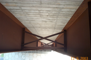
At the in-service stage, restraint is provided to the bottom flanges near supports (where they are in compression) either by U-frame action (deck slab plus web stiffeners) or by adding “knee braces” from the cross girders down to the bottom of the web. The choice will depend upon the relative depths of the main and cross girders, but it should be noted that knee bracing is relatively expensive to fabricate.
Cross girders providing torsional bracing
M6 Toll Bridge 443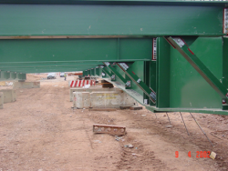
Knee bracing at supports (prior to erection)
M6 Toll Bridge 334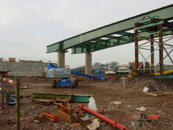
Narrow ladder deck torsional bracing
M6 Toll Bridge 450


For wide ladder decks with long cross girders, it will be more economical brace the cross girders than to increase the flange thickness. This can be achieved by pairing the cross girders with channel bracing at midspan.
[top]Stiffeners
Some basic rules for provision of stiffeners at preliminary design stage are given below.
[top]Provision

Porth Bypass, Rheola Bridge
Stiffeners are required along the main girders for the following:
- To limit the dimension of the web panel to control web buckling
- At support positions
- At positions of cross girders or bracings to form connections.
For ladder decks, the provision for the third requirement above usually deals adequately with the provisions for the first, so that once the bracings and cross girder arrangements are resolved, the resulting web stiffening is normally adequate.
Thin webs on multi-girder decks could need additional stiffeners in between bracing positions. However, UK fabricators will normally advise that it more cost effective to make the web thicker than to add further web stiffeners, if the provisions the third requirement do not provide sufficient control to satisfy the first.
UK practice is to use transverse (vertical) web stiffeners. Continental Europe often uses more extensive stiffening including longitudinal (horizontal) stiffeners. Normally, longitudinal (horizontal) stiffeners would not be considered economical in everyday highway bridge construction. (They may become appropriate for long span bridges, such as cable stayed bridges, to help control compression buckling of the web.)
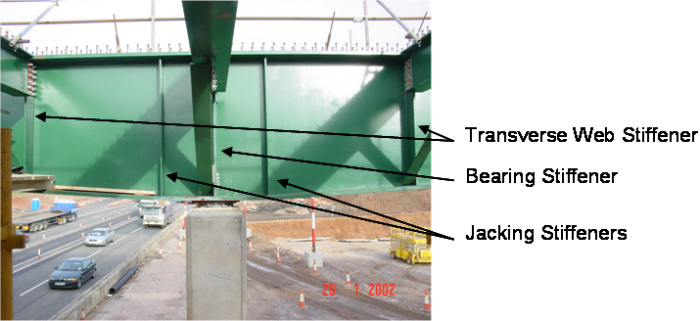
Transverse web stiffeners should be provided at the position of each cross girder or bracing.
Transverse web stiffeners at supports are usually referred to as bearing stiffeners. Additional stiffeners should be provided at positions for jacking for bearing replacement.

M6 Toll Bridge 450, ladder deck with knee bracing
[top]Proportions
Intermediate web stiffeners can commonly be proportioned as flat plates 250mm by 25mm or 200mm by 20mm thick: generally be proportioned in the ratio 10:1 width to thickness. This is convenient for the size of the top flange and for detailing bolted splice connections.
Where the stiffener is part of a U frame providing support to the bottom flange against buckling, then they may need to be larger.
Bearing stiffeners are usually thicker than intermediate web stiffeners as they need to resist additional lateral forces to be transmitted to supports. Bearing stiffeners will normally be between 30 and 50 mm thick.
[top]Deck slab
The most common way of constructing the deck slab is to use precast concrete permanent participating formwork. Other formwork includes glass fibre reinforced plastic (GRP) and traditional timber plywood, the latter being commonly used for irregular areas such as corners of skew bridges and cantilevers.
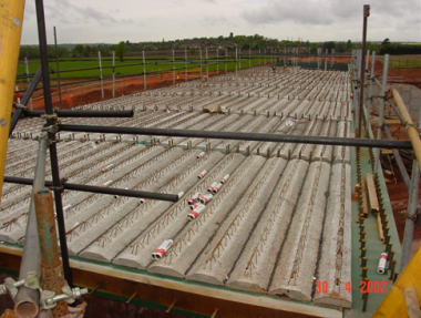
Precast concrete permanent formwork
M6 Toll, Bridge 295
Plywood formwork and traditional falsework system for edge cantilever construction
Porth Bypass, Rheola Bridge


Occasionally, a precast concrete cantilever system may be preferred to avoid falsework below the bridge deck level.
- Precast concrete edge beam and cantilevers
A650 Bingley relief Road, Cottingley Viaduct
A650 Bingley relief Road, Cottingley Viaduct


M6 Toll Bridge 501
The typical features of a bridge deck of this type will be:
- 250 mm overall thickness, (including precast concrete permanent participating formwork).
- Grade C40/50 concrete (to BS EN 206[9]).
- Reinforcement grade 500B (to BS EN 10080[10] and BS 4449[11]), typically 250kg/m³.
There are many aspects of the deck slab that affect the durability of the bridge: (concrete grade, cover, details to shed water away from critical areas). Durability and buildability should be considered at the preliminary stage - see CIRIA Report 155[12] and Report C543[13]. The combination of concrete grade and cover is important and careful reinforcement detailing is required to ensure that the correct covers are maintained. The top of the bridge deck has a waterproofing membrane applied.
[top]Articulation
Articulation is the way in which the bridge is arranged to deal with movements that occur as a result of actions on the bridge arising from:
- Temperature
- Wind
- Traffic loading (vehicles, trains, people)
- Self weight
Bearings are typically used to make the connection between bridge and supports, to accommodate rotations and movements arising from these effects, unless an integral support is provided.
Articulation needs to be considered at the preliminary design stage in order to determine where restraint forces will be provided, thus influencing design of support bracing systems and the substructure.
[top]Method of construction
The designer of a steel bridge has to determine the method of construction as this must be taken into account in the design of the steelwork. It is also incumbent upon the designer to indicate in the contract documents (usually on the drawings) the construction sequence assumed in the design, both for the erection of the steelwork and for the concreting of the deck slab. The principal options for bridge erection are:
- Erection by crane
- Launching
- Sliding
- Rolling
- Lifting large preassembled sections.
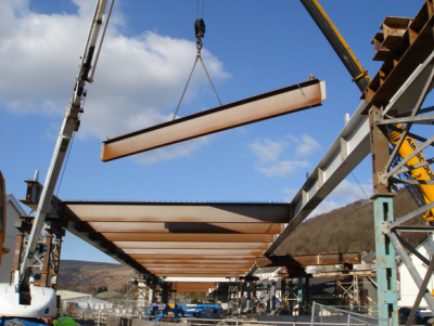
The most common method of erecting bridge girders is direct erection by mobile crane lifting the girders (termed erection pieces) from the ground onto the bridge substructure. Typically, girders for single span bridges will be placed either singly or in braced pairs spanning full length between the end supports. For multiple spans the girders are erected (again either singly or in braced pairs) in a span and cantilever sequence involving erection pieces that cantilever over the piers to the point of contraflexure in the next span as shown below.


There are physical limitations on the length of girder pieces that can be fabricated and transported to site. Under normal circumstances in the UK the maximum length for transport by road is 30m without a movement order but steelwork contractors are quite familiar with this procedure and girders up to 50m long have been transported by road.
When determining the most appropriate structural arrangement and associated erection method, the designer will be carry out hazard assessments and determine mitigation measures as required under the CDM regulations[1]. Guidance on the designer’s responsibilities and common hazards in bridge construction is given in CIRIA publication C604[14]. Guidance is also available in BCSA 38/05.
[top]References
- ↑ 1.0 1.1 Construction (Design and Management) Regulations (CDM) 2015
- ↑ CD 127, Cross-sections and headroom, The Design Manual for Roads and Bridges, The Stationary Office
- ↑ NA+A1:2014 to BS EN 1991-1-7:2006+A1:2014. UK National Annex to Eurocode 1. Actions on structures. Accidental actions. BSI
- ↑ PD 6694-1:2011+A1:2020, Recommendations for the design of structures subject to traffic loading to BS EN 1997-1:2004+A1:2013. BSI
- ↑ CD 377, Requirements for road restraint systems, The Design Manual for Roads and Bridges, The Stationary Office
- ↑ BS EN 10025: 2019 Hot rolled products of structural steels (in 6 Parts). BSI
- ↑ 7.0 7.1 7.2 BS EN 1993-1-1:2005+A1:2014, Eurocode 3: Design of steel structures. General rules and rules for buildings, BSI
- ↑ NA to BS EN 1991-2:2003, UK National Annex to Eurocode 1. Actions on structures. Traffic loads on bridges. BSI
- ↑ BS EN 206:2013+A1:2016 Concrete. Specification, performance, production and conformity. BSI
- ↑ BS EN 10080:2005 Steel for the reinforcement of concrete. Weldable reinforcing steel. General. BSI
- ↑ BS 4449:2005+A3:2016 Steel for the reinforcement of concrete. Weldable reinforcing steel. Bar, coil and decoiled product. Specification. BSI
- ↑ Ray, S.S; Barr, J.; Clark, L. (1996) Bridge detailing guide. (Report R155). CIRIA
- ↑ Souby, M. (2001) Bridges – design for improved durability. (Report C543). CIRIA
- ↑ CDM Regulations–work sector guidance for designers. (Report C604 Second Edition) 2004. CIRIA
[top]Resources
- Iles, D.C. (2010) Composite highway bridge design. (P356 including corrigendum, 2014). SCI
- Hendy, C.R.; Iles, D.C. (2015) Steel Bridge Group: Guidance Notes on best practice in steel bridge construction (6th Issue). (P185). SCI
- BCSA Guide to the erection of steel bridges (38/05). BCSA
- Steel Bridges: A practical approach to design for efficient fabrication and construction. (51/10). BCSA
- Chapter 1: Design conception
- Preliminary steel bridge design charts:
- Chart finder
- Spreadsheet tool
- User manual
- All three of which can be found on the BCSA web site
[top]See also
- Multi-girder composite bridges
- Ladder deck composite bridges
- Integral bridges
- Material selection and product specification
- Weathering steel
- Bracing systems
- Stiffeners
- Connections in bridges
- Bridge articulation and bearing specification
- Plan curvature in bridges
- Skew bridges
- Design for steel bridge construction