


Car parks
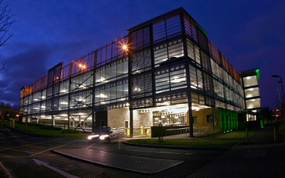
Multi-storey car parks are commonly found at railway stations, airports, hospitals and in city centres. They form parts of mixed-use developments, retail and entertainment centres. Car parks should be easily identifiable for potential users but at the same time be integrated in the overall urban design. Car park structures are usually above ground normally as permanent structures although there is growing demand for temporary/demountable car parking. Underground and basement car parking is also used, mainly in city centres where high land values make this financially viable.
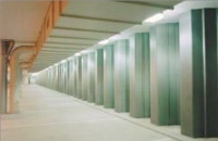
Multi-storey car parks are unique buildings in which all elements of the structure are normally exposed to the public. Little weather protection is required and the top floor is generally uncovered. The building is subject to heavy wear from traffic and chemical attack from de-icing salts that can create severe exposure conditions, which should be taken into account when detailing the building.

(Image courtesy of Kloeckner Metals UK Westok)
[top]Attributes of good car park design

(Image courtesy of Kloeckner Metals UK Westok)
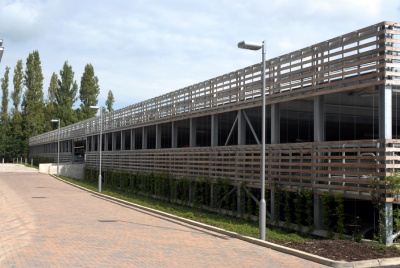
The car park is the first building many visitors to a venue or a town/city centre come into contact with and first impressions count! Although the functional requirements of multi-storey car parks have a strong influence on the building form, they should be expressed in good quality, creative design which reflects their importance in creating a good first impression. Where required, a range of cladding options is available to meet any specific local planning requirements. In urban and city centre locations, the building should blend into the environment or, as is often the case where planning allows, contemporary innovative envelope designs are used to great effect.
Good car park design should include the following attributes:
- Easy entry and egress to the car park and the parking stalls
- Uncomplicated and logical traffic flow around the car park
- Unimpeded movement
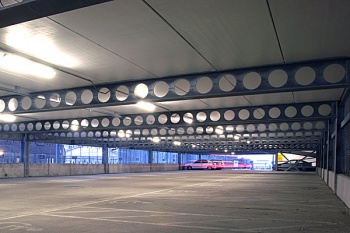
- Light and airy
- Low maintenance
- Safe and secure.
[top]Advantages of steel construction

(Image courtesy of Bourne Parking Ltd.)
Steel construction is well placed to satisfy all the requirements of good car park design. Steel is:
- Ideal for long spans – providing column-free parking space
- Lightweight – reducing foundation requirements
- Robust and fire resistant
- Fast in construction – particularly relevant where the venue that is to be served is to remain operational during construction, e.g. retail, stations and hospitals
- Easily maintained
- Vandal resistant
- Modular steel systems are available for demountable structures
- Economic.
Steel construction also has many generic benefits that are relevant to car park buildings.
[top]Design
[top]The design brief
It is important that the clients’ requirements are reviewed by the whole design team at the outset of the project. Technical and financial feasibility studies should be carried out before proceeding with a detailed design so that the viability of the project can be confirmed. On completion of the feasibility stage, the entire brief should be reviewed and any necessary changes agreed, bearing in mind initial and whole life costs, service life, safety and security, etc.
The precise use of the car park and the client’s objectives should be stated clearly in the brief. A car park can be used for a number or a combination of uses, like the provision of a parking facility for a specific development, a public car park built for profit, with a constant pattern of use or experiencing peak demands at certain times.
The type and mix of vehicles likely to use the car park needs to be defined as well as the likelihood of any special requirements for vehicle with non-standard dimensions. Consideration should also be given to the potential for the future development of the car park.
[top]Outline design
Outline design considerations are mainly related to the configuration of parking bays and traffic flow patterns into and around the car park.
The dimensions of large, standard and small size cars are well established and are given by the Institution of Structural Engineers[1]. These dimensions form the basis of the geometry required for stalls, aisles and ramps. The minimum dimensions based on a standard car, the bin width, the parking angle and stall width are shown in the following table. Bin width is defined in the diagrams which follow.
| Parking angle | Stall width (m) | Stall width (m) parallel to aisle | Aisle width (m) | Bin width (m) for stall length 4.80m |
|---|---|---|---|---|
| 45o | 2.3 | 3.25 | 3.6 | 13.65 |
| 2.4 | 3.39 | 13.80 | ||
| 2.5 | 3.54 | 13.95 | ||
| 60o | 2.3 | 2.66 | 4.2 | 14.85 |
| 2.4 | 2.77 | 14.95 | ||
| 2.5 | 2.89 | 15.05 | ||
| 75o | 2.3 | 2.38 | 4.98 | 15.45 |
| 2.4 | 2.49 | 15.50 | ||
| 2.5 | 2.59 | 15.55 | ||
| 90o | All widths | All widths | One way aisle 6.0 | 15.60 |
| 90o | All widths | All widths | Two way aisle 6.95 | 16.55 |
Dynamic efficiency
The dynamic efficiency of a car park depends on the ease with which entry, egress and parking can be achieved. The general principle should be that cars cover as many stalls as possible on entry and as few as possible on exit. The layout of the exits and the size of the reservoir capacity are other major factors when considering dynamic efficiency.
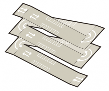
Flow patterns
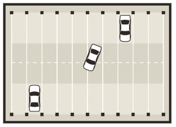
There are two flow patterns used in modern car park construction: one way and two-way flow. These can be combined with either 90° or angled parking.
One-way flow systems, if used with angled parking, provide a very good solution to the parking problem. They ensure easier entry and exit to stalls and allow significant flow capacities to be achieved with the self-enforcing flow pattern. Difficulties can arise when the intended flow is ignored and therefore good signage is required.
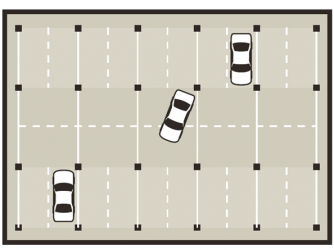
Two-way flow systems are more familiar to the user and if properly designed can achieve a higher flow rate than one-way systems. They require marginally more space and are therefore less structurally efficient than one-way systems. Two-way systems are best used with 90° parking as their use with angled parking can cause confusion to the driver.
- Flow patterns
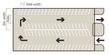
One way flow, angled parking
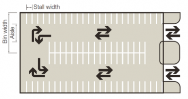
Two way flow, 90° parking


[top]Circulation design

Ramp width and slope
The widths of the ramps should usually be no less than 3.5m for a single ramp and 7m for a double ramp. It is recommended that ramp widths are kept in line with stall widths, for example with single flow traffic, the ramp would be two stall widths wide and for two way traffic flow, three stall widths wide.
The slope of the ramp is dependent on the clear headroom (2.1m minimum) and the structural zone. The growth in popularity of the larger multi-purpose vehicles (MPV’s) has had an effect on the minimum clear height and ramp length requirements. The shallower and wider the ramp is, the better it will meet the needs of users. However less steep ramps are longer. Typical slopes range from 1:6 to 1:10. Steeper gradients may be used if transitions are provided at the top and bottom of the slope.
Reference may be made to an Institution of Structural Engineers publication[1] for detailed guidance on ramp widths and slopes.
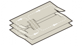
The split-level system offers a method of reducing ramp length, whilst keeping the gradient within reasonable limits by staggering the parking levels by half a storey height.
Car park layout
There are many layouts used for multi-storey car parks, each offering specific advantages to the user and operator. The layouts indicated are those most commonly used in the UK. All are eminently suited to a steel-framed solution, which will be competitive on price and provide excellent performance.
Split-level layouts have good dynamic flow rates and excellent structural efficiency. They can be used with one-way and two-way circulation patterns and a variety of ramp arrangements to achieve the desired performance. This is probably the most popular layout in the UK for car parks with row capacities greater than 24 cars. Entry and exit traffic are separated and the flow pattern is simple and uncomplicated. When built in steel, with column free spans, this layout will generally give the best combination of economy and operating efficiency.
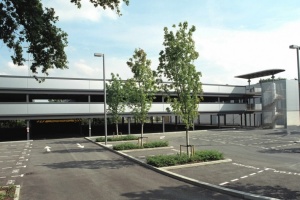
Flat deck layouts are becoming increasingly popular for their simplicity of construction, clean lines and ease of use. They are particularly suitable in situations where the floor levels have to be matched to a neighbouring building. This layout is less efficient than the split-level arrangement but can have comparable dynamic capacity for infrequent users. However the larger search paths can be frustrating for frequent users where a ‘parking ramp’ solution may be more acceptable. Flat deck layout would be used for smaller car parks where the dynamic capacity is not critical. Two-way flow is used with external rapid entry and exit ramps.
- Flat deck layouts
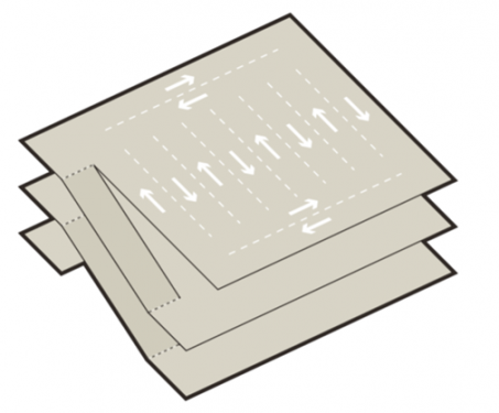
Flat deck layout
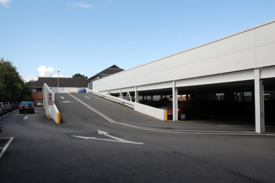
Flat deck car park – Waitrose, Maidenhead
(Image courtesy of Bourne Parking Ltd.)


Parking ramps may be used with great success where frequent users are the prevalent customers, for example, a car park serving a large office building. Their main advantage is that the user must pass all stalls on entry to the car park, resulting in a rapid search path and less frustration. Users can be disadvantaged when exiting the car park unless an express exit is provided.
The parking ramp shown is a single ramp with two-way flow. It offers ease of use combined with efficient usage of space. External ramps may be added if rapid exit from the park is required. In this case a one-way system would be preferred.
Whichever type of layout is chosen, a number of key principles should be followed:
- Keep it simple. What looks like a clever solution could be difficult for the user
- Minimise the workload on the driver and avoid confusion as to where to go and what to do. This is solved partly by signs but mainly by good design
- Cover as many stalls as possible on the entry route
- Pass as few stalls as possible on the way out
- Separate inward traffic from outward traffic if possible, without causing additional complications
- Circulate to the right if possible so that the driver is on the inside of the turn.
Single deck, flat plate car park with an internal ramp – GreenPark, Reading
(Image courtesy of Bourne Parking Ltd.)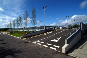
Colbalt business park, Newcastle
(Image courtesy of Bourne Parking Ltd.)


[top]Structural form

(Image courtesy of Bourne Parking Ltd.)
The structural design of a car park will usually determine its quality as a user-friendly structure. The structural form should provide:
- Ease of entry and egress to and from stalls so that users can gain rapid entry and exit without the risk of damage to vehicle or injury to person.
- Few obstructions to movement. The driver should be guided through the park without encountering severe obstructions such as columns in the drive path and badly parked cars caused by inefficient design or layout.
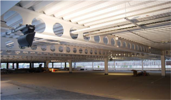
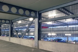
- A light and airy environment. The environment the car park provides will often determine how profitable it is. A light and airy environment should be one of the major goals of the car park designer. Steel is ideally placed to provide this type of environment because of its lightweight nature and long span capabilities. This can be further enhanced if open web sections are chosen.
- A safe and secure environment. A building with minimal internal structure will help to enhance the feeling of security by making the area as open as possible with few barriers to sight lines. The light and airy environment made possible with steel will help to enhance the feeling of security required of these buildings.
[top]Loading
The British Standards for structural design were withdrawn in 2010 and replaced with harmonised European standards. The withdrawn British Standards will no longer be updated, but Approved Document A[2] makes it clear that they can still be used.
Once the appropriate suite of of standards has been chosen; it should be used exclusively throughout the design and construction process.
The imposed loading for the parking areas and ramps in car parks is given in BS EN 1991-1-1[3] with its National Annex[4]. For a normal mix of vehicles, taking the maximum weight of any vehicle as 2500kg, the imposed uniformly distributed load given in BS EN 1991[3] is 2.5kN/m2.
Vehicle impact
The structure of the car park may be subject to vehicle impact either directly or through transmission from the edge protection barriers. The impact may also be applied at ground level from outside of the car park. Equivalent static design loads to allow for vehicular impact are provided in Section 4.3 of BS EN 1991-1-7[5].
All car parks should be fitted with adequate vehicle safety barriers to prevent accidental damage to the structure to and restrain out-of-control vehicles. Edge barriers in particular should be adequate to restrain vehicles and be of a height and design, which will safeguard small children. BS 6180[6] may be of assistance.
Foundations
The loading on foundations is greatly influenced by the material chosen for the superstructure. Steel is the lightest practical construction material for car parks and will often allow the use of simple foundations where other, heavier materials will not. The type of foundation required is often the deciding factor on whether a project is economically viable and therefore steel construction is often the only viable solution for many multi-storey car parks.
[top]Column positions
The optimum stall configuration and flow characteristics of multi-storey car parks can only be realised if there are no internal columns. If steel is chosen as the frame material a clear span solution can be used for the majority of car parks.
No internal columns to impede traffic flow
Alternative positions of columns impede traffic (2 stall width spacing)


However there may be occasions, for example, where the car park is beneath another form of structure with a different span arrangement, where internal columns must be used. The arrangement of columns has an impact on the building size and its parking capacity. A comparison of possible geometry for clear span and propped alternatives is presented in the table below.
| No. of stalls between columns | Column centres for clear span | Column centres for propped span |
|---|---|---|
| 2 | 4.8m | 5.7m |
| 3 | 7.2m | 8.1m |
| 4 | 9.6m | 10.5m |
Based on:
- 2.4m stall width
- 0.3m clearance from edge of stall to column face (for propped span only)
- 0.3m column width (for propped span only)
It is generally preferable to arrange longitudinal column and beam spacings to coincide with parking stall widths; the equivalent of one, two or three stall widths are the most commonly used. Using a single width has the advantage of visually separating the stalls for the driver, but it is not suitable when using internal columns. With column spacing of two stall widths it is generally only necessary to use secondary beams when shallow profile steel decking is used to form the slab. Other slab solutions may require secondary beams when the column spacing is in excess of two bay widths. Secondary beams are used to avoid propping of the floor during construction, to limit depth of construction and ensure economy of design.
- Steel framed, multi-storey car park, Southmead
(Image courtesy of Bourne Parking Ltd.)
(Image courtesy of Bourne Parking Ltd.)


[top]Floor & frame solutions
A variety of floor systems can be used in multi-storey car park construction. The ultimate choice will depend upon many factors, such as height restrictions and structural layout. Five of the most common types of floor construction used in steel-framed car parks are described below. In all five systems the steel beams may generally be designed either compositely or non-compositely. The exception is where precast units run parallel to the primary beam, in which case the primary beam will be a non-composite design.
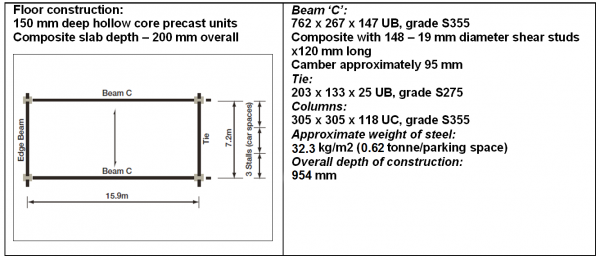
[top]Hollow core pre-cast units used compositely with the steel beams
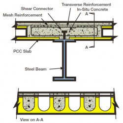

To achieve composite action, alternate cores of the precast units must be broken out and filled with in-situ concrete for the effective width of the slab. Additional transverse reinforcement is also required. A concrete topping would normally be used to give adequate resistance to moisture penetration and to tie the precast units together to form a monolithic floor slab. Detailed guidance is available in SCI P287.
The system has the advantage that wider spacing of main beams can be achieved because of the precast unit's spanning capabilities, and low self weight. Speed of construction will be improved over a solid slab, leading to greater cost savings on the scheme. In the non-composite version of this system the cores of the precast units do not require to be broken out, this leads to faster construction times at the expense of greater steel weight.

[top]Steel deck with composite beams

The shallow profile steel decking solution has been used for a small number of car parks in the UK. As well as performing a role as part of a composite slab, the steel deck also acts as permanent formwork to improve speed of erection and reduce cranage requirements compared with the other systems described. The maximum unpropped span of these types of deck is around 4.5m (consult manufacturers' literature for exact details), therefore the spacing of the main beams cannot be greater than one stall width unless secondary beams are used.
When steel deck is used, through deck welding of the shear studs is beneficial because it enables continuous sheets of steel deck to be laid on the steel beams prior to fixing the studs. It may also enhance the way in which the deck behaves as transverse reinforcement adjacent to the studs. However, in the potentially corrosive environment of a car park, the need, when using through deck welding, to keep the upper surface of the beams free of paint (to avoid contamination of the stud welds) may be unacceptable. This leaves the designer with four options:
- Use shear connectors that are attached to the beams without the need for welding. A number of connectors that use shot-fired pins are available.
- Weld the studs to the beams in the fabrication shop, prior to applying the corrosion protection. With this solution the deck is best laid in single span lengths and butted up to the studs. This makes the deck less structurally efficient and requires stop ends to prevent the in-situ concrete escaping through voids. Alternatively, holes may be punched in the deck so that it can slot over the studs, but this may be difficult to achieve in practice.
- Use non-composite beams.
- Use a combination of non-composite secondary and Composite primary beam. The decking can then be laid in continuous lengths across the secondary beams, which are normal to the span of the primary beams.


(Image courtesy of Bourne Parking Ltd.)
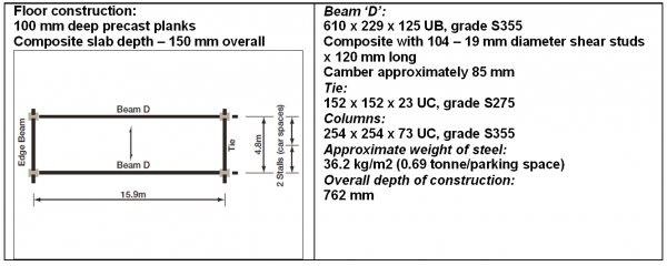
[top]Composite beam with composite pre-cast concrete slab and topping
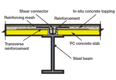

The pre-cast slab in this case is solid and usually only 75mm to 100mm thick. This spans between beams, the maximum span being around 5m, allowing main beams to be spaced at two stall widths, without propping of the slab during construction. Composite construction is achieved with shear connectors welded to the top flange of the beam. These should be welded ‘in the fabrication shop’ so that corrosion protection can be applied after they have been attached. Transverse reinforcement will be required and additional bars may also be required at the stud location to act as bottom reinforcement.
[top]Precast slab system
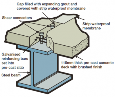

A variation on the pre-cast slab design is the 'BourneMontex' system as illustrated. This is a proprietary design using special slabs with hooped bars emerging from the ends of the units. These hoops are used to tie the system together. The void is filled with in-situ concrete and then covered with a strip waterproof membrane.
[top]Sizing of the structural members
This section provides guidance on sizing structural members for various car park layouts. The designs are based on the following assumptions:
- Design is given for internal and edge beams where appropriate for one bay of a car park
- Imposed loading is taken as 2.5kN/m2
- No account is taken of pattern loading
- Grade S355 is used for all main and secondary beams
- Grade S275 is used for all ties
- Approximate weights of steel given are based on a car park 72m long x 32m wide with car parking spaces at 2.4m wide. An allowance of 4% for connections and bracing has been assumed
- All in-situ concrete is normal weight, grade 50
- Beams and slabs are unpropped (vertically)
- Column sizes are based on the lower length of a 4-storey car park
- Beams have been chosen to give a minimum frequency of 3.0Hz
- Imposed load deflection limit: Span/360
- Total load deflection limit: Span/150
- Pre-camber approximately equivalent to deflection due to dead load + 1/3 deflection due to imposed load
The structural sizes presented for layouts 1 to 4 have been derived on the assumption of balanced loading and effective temporary restraint of the compression flanges during construction. For further guidance see SCI P287.


[top]Deflection

(Image courtesy of Bourne Parking Ltd.)
Where clear span construction and high strength steels are used for the main beams, deflection may govern the design. Beams may therefore be pre-cambered to compensate for dead load deflection and to minimise the risk of ponding, when in-situ concrete solutions are used. An additional pre-camber may be introduced to compensate for a proportion of the live load deflection (usually up to 1/3). This has the advantage that the beams have a slight upward bow, which avoids the optical illusion of a heavily deflected beam when it is, in reality, level. The theoretical deflections, allowed for in pre-cambers, do not always occur and care must be taken to ensure that any permanent set does not impede the efficient drainage of the slab.
[top]Dynamic performance

The dynamic performance of floors in buildings has become an important issue in recent times, which has led to a review of design practice in this area. In buildings such as hospitals, the dynamic performance can be critical, but in buildings such as car parks, where there is an expectation of disturbance from traffic movement, it is much less important. The human perception of movement in a car park will be less than in other situations because users are either in motion themselves, by walking, or sat in a car and isolated from external vibration by the suspension.
Traditionally, steel-framed car parks have been designed using a minimum natural frequency as a sole measure of dynamic performance. SCI P354 suggests the minimum natural frequency of the floor (including the concrete slab, primary and secondary beams, where appropriate) should not be below 3 Hz. Guidance from the Institution of Structural Engineers[1] suggests an increase to the minimum of 5 Hz, but it appears that this is not based on any adverse comment from users or owners.
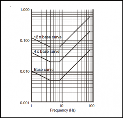
For vibration, consideration of natural frequency alone can be misleading, as it is the amplitude of vibration that most people feel. The amplitude can be expressed in terms of displacements, but, in practice, this can be difficult to measure. As a consequence, most modern Standards describe the sensitivity of human exposure to vibrations in terms of acceleration amplitudes. In BS 6472[7], accelerations are expressed relative to a ‘base value’, which is adjusted with frequency according to human perception, so forming a ‘base curve’, as shown.
The ratio of the predicted (or measured) acceleration to the base curve value is then defined as a ‘response factor’. A variety of response factor values are recommended for different floor types, but there are no recommended values for car parks in BS 6472[7].
To compensate for this ‘omission’, a study was made of nine steel-framed car parks incorporating long spans. All were constructed in the last 15 years, with no adverse comment about the dynamic behaviour being known. The examples included seven car parks with composite beams and precast units (with a concrete topping or asphalt finish), and two with composite beams and a concrete slab using steel decking as permanent shuttering. Secondary beam spans ranged from 15.6m to 28m, and floor slabs spanned between 3.6m and 7.2m. The most onerous floor area in each example was chosen to calculate the natural frequency and the corresponding response factor. An ‘empty’ case (assuming 1.1% damping) and a ‘full’ case (assuming 2.5kN/m2 imposed loading and 4.5% damping) were considered.
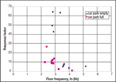

The results of the study are shown left. Floor natural frequencies ranged from 2.8 to 5.18Hz ‘empty’ and 2.2 to 4.2Hz ‘full’. The natural frequencies tend to be lower under full loading because of the higher mass mobilised. Response factors ranged from 3.6 to 64.5 for the ‘empty’ cases and 0.9 to 26.6 for the ‘full’ cases. The ratio of the natural frequency ‘full’ to ‘empty’ was nearly always about 0.8, which merely reflects a consistent ratio of dead loading only to full loading of 0.64 for car park construction. Response factors are generally higher for the ‘empty’ case, where the mass and damping is less.
The results clearly show that there has been a recent history of car park construction with low natural frequencies and high response factors, which have received no adverse comment. The study shows that the traditional natural frequency value of 3Hz can be maintained for design, and used with confidence. For normal steel-framed solutions, the adoption of this value leads to bare floors (damping 1.1% with no imposed load) possessing a maximum response factor of approximately 65. This value can be used as guidance where more detailed calculations are deemed to be appropriate. No guidance is given for a full car park because the characteristics are different and it is considered that design based on the criterion for the empty case is sufficient.
Further information on floor vibrations is available in Steel Construction: Floor Vibration, and a useful web-based Floor response calculator is also available to swiftly evaluate the vibration response of floors.
In addition to human/car-induced vibration, excitation may be caused by impact from cars running over uneven surfaces or discontinuities, such as expansion joints. Careful detailing and workmanship should ensure that any joints are level and can be traversed smoothly, and that the gaps are no larger than necessary. Regular maintenance should prevent the wearing surface from deteriorating.
[top]Stability and robustness

(Image courtesy of Bourne Parking Ltd.)
The stability and robustness of a structure is a vital structural design consideration. Multi-storey car parks pose a particular problem because they contain few internal walls. This is especially true of demountable structures. There are various methods to ensure structural stability against horizontal forces; two of the most common options are outlined below.
Braced structure
Suitable bays or cores are placed around the building to provide stability in two orthogonal directions. Bracing may take the form of cross members or eccentric type bracing. In car parks the eccentric bracing can be used across the structure because it allows relatively unimpeded circulation throughout the floor area.
Unbraced structure
In this case the frame is designed as 'rigid'. Moments are transferred from beams into columns via moment connections and stability is gained from the stiffness and continuity of the connections. This may result in the need for haunches in clear span construction.
A combination of these methods may be used. For example, use a rigid frame across the structure and brace longitudinally at the outside edge of the building.
Whichever method of achieving stability is chosen, it is important to consider the construction stage of the building as well as the completed structure. The floor slab in most cases is designed to carry the horizontal forces to the braced parts of the structure. Until this plate has gained sufficient strength it may be necessary to provide temporary plan bracing.
Relevant codes of practice should be followed to ensure adequate provisions for robustness of car park structures are ensured. In the UK, Approved Document A[2] and the codes of practice for construction materials should be referred to for measures against disproportionate collapse. More information on this issue is provided in SCI P391.
[top]Fire resistance
For the purposes of fire precautions, car parks can be either open or other. Open car parks have relatively low structural fire resistance requirements whereas the requirements for other car parks are typically consistent with those demanded of commercial buildings of the same height.
Open sided car parks are defined in Approved Document B[8](England and Wales) as having open ventilation of at least 5% of the floor area at each level, a minimum of half of which should be in opposing walls. The same definition applies in Scotland and Northern Ireland. The standard structural fire resistance requirement for car parks less than 30m in height (less than 18m in Scotland) is 15 minutes. Most hot rolled sections are deemed to achieve 15 minutes fire resistance without added fire protection although a small number of sections at the lower end of the range will do so only when less than fully loaded. In general, where a section does not have 15 minutes inherent fire resistance, it is usually more cost effective to increase the section size and/or grade than to fire protect.
The relatively benign requirements for fire resistance in open car parks are based on the results of a global programme of natural fire tests. These tests demonstrated that fires in open car parks do not generate high temperatures and that most unprotected steel in open steel-framed car parks has sufficient inherent resistance to withstand the effects of any fires that are likely to occur. These have been well documented[9] and are summarised here.
| Country | Maximum measured steel temperature | |
|---|---|---|
| Beams | Columns | |
| UK | 275oC | 360oC |
| Japan | 245oC | 242oC |
| USA | 226oC | . |
| Australia | 340oC | 320oC |
These can be compared with failure temperatures of 550°C for columns and 620°C for beams in standard fire tests.
The fire resistance requirements for other car parks vary between authorities, but are typically, 30 minutes, 60 minutes or 120 minutes depending on the height.
[top]Durability

(Image courtesy of Kloeckner Metals UK Westok)
A car park should be designed to give the best possible return on investment and should therefore be maintenance free as far as possible. Maintenance requirements, and how they should be carried out, are described by the Institution of Civil Engineers[10]. Maintenance is of particular importance to ensure that drainage gullies and downpipes are clear of debris to enable water to drain efficiently from the car park.
Car parks, by their very nature exist in environments that are far from ideal. The air is often contaminated with fumes from car engines. The surfaces of the structure may be sprayed with water (from wet vehicles), which in winter can be contaminated with de-icing salts and other highly corrosive elements that can percolate through cracks in the concrete slab. Although the effect of these can be minimised by good drainage design, crack control, and/or the application of protection to the top surface of the slab, it is still necessary to give complete protection to those components within the car park, which are likely to be in close contact with these contaminants. The major elements are the steel frame and the concrete, or composite floor slabs.
[top]The steel frame
Steel is a durable framing material. It will, if protected correctly, give a long life with minimal maintenance. In most cases all that is required is a repaint at the first maintenance period, which can be 20 to 30 years or more, depending on the initial protection specified. The durability of the corrosion protection system is primarily influenced by the corrosivity of the environment, which is categorised in ISO 12944 Part 2[11] and BS EN ISO 9223[12]. A number of standard systems for buildings are available for a range of corrosivity categories. For structural steelwork in car parks, which are effectively exterior environments, corrosivity categories C3, C4, or C5 may be appropriate. Examples of such standard systems for a C3 corrosivity category are given in the table below.
| System number | E-C3-A | E-C3-B | E-C3-C |
|---|---|---|---|
| Coating life | 20+ | 20 | 20 |
| Nearest equivalent BS EN ISO 12944-5[13] | - | C3.07 | C3.09 |
| Surface preparation to BS EN ISO 8501-1[14] | - | Blast clean to Sa 2½ | Blast clean to Sa 2½ |
| Factory applied coatings | Hot-dip galvanize to BS EN ISO 1461[15] (notes 1 & 2) |
i) Zinc phosphate epoxy primer 80μm (note 3) ii) High build epoxy MIO 100μm |
i) High build zinc phosphate epoxy primer 100μm (note 3) ii) High solid aliphatic polyurethane finish 60μm |
| Site applied coatings | - | Recoatable polyurethane finish 60μm | - |
Notes to table:
- For steel profiles over 6mm thick the minimum average thickness of galvanized coatings to BS EN ISO 1461[15] is 85µm.
- Where painting of galvanized steelwork is required for aesthetic or other reasons; suitable systems from BS EN ISO 12944-5[13] may be used.
- The thickness values given for primers are the total thickness used and may include a prefabrication primer. For example, 80µm can be in one coat or as 20µm prefabrication primer plus 60µm post fabrication primer.
[top]Concrete floors
The concrete within a car park is particularly susceptible to deterioration, so grade 50 concrete should usually be specified. Precast units are generally more durable than in-situ concrete due to factory controlled production conditions. It is recommended therefore, that one of the pre-cast systems previously described (Composite beam with composite pre-cast concrete slab and topping or the 'Montex' system) should be used with a limited amount of structural topping. To minimise the percolation of corrosive fluids through cracks, floors should be sloped at 1:60 falls to aid drainage, and the top surface of the concrete slab should be protected with an appropriate proprietary waterproofing system. Manufacturers guidance should be followed for the correct choice of product and application.
[top]Metal decking

(Image courtesy of Bourne Parking Ltd.)
G275 galvanizing (275g/m2 of zinc) is the standard protective coating for steel decking used in composite construction. This level of corrosion protection to the upper surface of the decking will be sufficient, provided adequate provision has been made to prevent the ingress of water (using reinforcement to control cracking, and waterproofing the top surface of the concrete).
The underside of the decking should be given additional protection in the form of a pre-applied coating or epoxy paint applied in-situ. Such an additional layer of protection has the advantage that it can be regularly inspected and remedial work undertaken if required. However, it is recommended that Tata Steel be consulted on durability and future maintenance issues at an early stage if this solution is to be adopted.
This decking can be white enamelled or plastisol coated on the underside to make the car park light and bright.
[top]Waterproofing


(Image courtesy of Bourne Parking Ltd.)
Car parks require treatment against the effects of the external climate. The car park environment can be very onerous, especially where aggressive snow and ice clearing methods are adopted. It is therefore recommended that at least the top deck of the car park is waterproofed with a traditional bituminous membrane or liquid applied seamless coating. It is also good practice to treat other floors to prevent ingress of water. It is important to specify the correct product and ensure that installation and maintenance are fully in accordance with the supplier’s recommendations.
With all floors it is necessary to provide adequate falls and drainage to prevent the build up of water on the slabs.
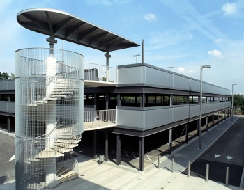
There is a growing trend to use a lightweight roof over the top parking deck. This gives added protection to the top floor of the car park allowing users to park in all weathers. The aesthetic appeal of a car park can be significantly enhanced by providing a roof enabling the car park to blend in with the urban environment. The long-term benefits of reduced maintenance can far outweigh the initial cost of this approach. The car parks at Aylesbury and Guildford typify this method of construction.
- Car parks with a lightweight roof over the top parking deck

946 space Car Park adjacent to railway and local housing in Guildford

600 spaces on 5 levels developed by Safeway Stores plc for Aylesbury Vale District Council


[top]Refurbishment
One of the major advantages of steel buildings is the ease with which they can be refurbished and adapted. Car parks in steel are no different in this respect. There are many examples where steel-framed car parks have been refurbished with minimal expense, such as the refurbishment of the Waitrose car park at Weybridge.
- Refurbishment of the Waitrose car park at Weybridge

Before refurbishment

After refurbishment

Refurbished interior


[top]Commercial viability
The cost of a structural steelwork in real terms has decreased appreciably over the last few years through greater efficiency in both the steel manufacturing and fabrication industries. The shorter construction period made possible through the use of a steel frame and consequently the earlier return on investment increases the commercial viability. The elimination of fire protection costs has had a major influence in making a steel-framed car park one of the most competitive options available.
[top]Other types of car parks
[top]Underground car parks

Steel sheet piles are ideal for producing an efficient, cost effective and quick retaining structure for underground car parks and deep basement car parks. Floors can be designed to act as struts for the finished structure, which can be utilised in the ‘Top Down’ construction method.
This combined with the ability of a steel sheet pile retaining wall to accept vertical bearing loads make this form of construction particularly effective for car parks beneath new buildings. Further information on underground car parks is contained in SCI P275.
[top]Demountable car parks
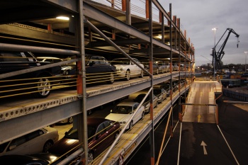

(Image courtesy of Bourne Parking Ltd.)
Growing car ownership in the UK is resulting in the need to provide a greater number of car parks and more multi-storey car parks. Large companies and institutions especially, have a growing need for larger parking facilities. This need may be met in many cases by the use of demountable structures, to give an eminently flexible solution to the parking problem.
In addition, demountable steel structures are increasingly used to provide temporary car parking where new permanent car park structures are being built or existing structures are being refurbished. Examples include supermarkets, hospitals, stations and airports.
For commercial buildings this makes very good sense. It is estimated that for a large supermarket, a single parking space leads to the generation of around £5,000 per week in turnover. A loss in parking capacity of 100 or 200 spaces can therefore result in lost revenue of £0.5m to £1m per week!
Steel is considered to be the only practical solution that can be constructed as demountable and gives the following benefits:
- Floor decks are modular and provide 16m clear spans
- The modularity provides flexibility in terms of size and ramp and staircase location
- Floor decks are cambered and incorporate a fully managed drainage system
- In most cases, when sited on existing car parks, no foundations are required.
There are a number of specialist companies offering temporary steel car park solutions.
[top]Wholly automatic multi-storey car parks
This form of car park requires only around half the volume of a conventional car park to store the same number of cars and therefore is increasingly attractive and viable in city centre locations. This is because these steel-framed car parks do not require access ramps or roadways within the car storage area. The driver parks the cars on a robot trolley within an entrance module. From this point the trolley takes the car to an empty parking space. When the driver wants the car back, it is retrieved by a robot trolley and returned to an exit module.
Construction is simply a steel framework with cladding to match the local environment. Since this form of car park requires less energy to run, operating costs are lower than for a conventional car park. This form of car park can be built either above or below ground.
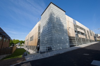
[top]Aesthetic design
In addition to aesthetic appeal, local planning constraints may require car parks to be clad in certain materials to blend in with the urban fabric. Steel car park structures can be designed to accept all types of external cladding from timber to brick work and wide range of metal products including:
- Plastic-coated steel sheets and panels
- Wire mesh panels
- Perforated sheets
- Stainless steel sheets and panels
- Aluminium sheets and panels.
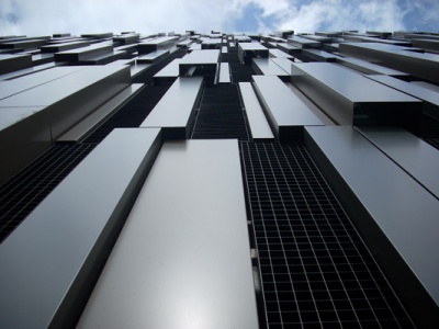

(Image courtesy of Bourne Parking Ltd.)
Metallic cladding is often preferred because they are light and open and because of their variety and innovative nature. Recent examples include the addition of solar panels, and LED lighting and green walls. All metallic cladding systems are compatible with steel frames.
Brick cladding of steel frames is well proven for offices, car parks and many other structures. Steel’s inherent accuracy is a positive advantage when attaching brickwork support systems.
The cladding may be designed to be load bearing as well as aesthetic. In particular crash barriers have been designed as an integral part of the cladding system. These may be load resistant (stiff) or energy absorbing (flexible). The steel frame provides an excellent interface for connection of either type.
[top]Case studies


[top]References
- ↑ 1.0 1.1 1.2 Design recommendations for multi-storey and underground car parks, 4th ed, the Institution of Structural Engineers, 2011
- ↑ 2.0 2.1 Approved Document A (Structure) 2004 Edition incorporating 2004, 2010, and 2013 amendments. Ministry of Housing, Communities & Local Government
- ↑ 3.0 3.1 BS EN 1991-1-1:2002 Eurocode 1. Actions on structures. General actions. Densities, self-weight, imposed loads for buildings. BSI
- ↑ NA to BS EN 1991-1-1:2002 UK National Annex to Eurocode 1. Actions on structures. General actions. Densities, self-weight, imposed loads for buildings, BSI
- ↑ BS EN 1991-1-7:2006+A1:2014 Eurocode 1. Actions on structures. General actions. Accidental actions. BSI
- ↑ BS 6180:2011 Barriers in and about buildings. Code of practice. BSI
- ↑ 7.0 7.1 7.2 BS 6472-1:2008 Guide to evaluation of human exposure to vibration in buildings. Vibration sources other than blasting. BSI
- ↑ Approved Document B (Fire safety, Volume 2 – Buildings other than Dwellings), 2019 edition incorporating 2020 amendments – for use in England . Ministry of Housing, Communities & Local Government
- ↑ Fire safety in open car parks. No. 75. European Convention for Constructional Steelwork.
- ↑ The inspection and maintenance of multi-storey car parks, National Steering Committee on the Inspection of Multi-storey Car Parks, ICE, 2002
- ↑ BS EN ISO 12944-2:2017 Paints and varnishes - Corrosion protection of steel structures by protective paint systems. Classification of environments, BSI
- ↑ BS EN ISO 9223:2012 Corrosion of metals and alloys. Corrosivity of atmospheres. Classification, determination and estimation. BSI
- ↑ 13.0 13.1 BS EN ISO 12944-5: 2019, Paints and varnishes, Corrosion protection of steel structures by protective paint systems, Protective paint systems, BSI
- ↑ BS EN ISO 8501-1:2007 Preparation of steel substrates before application of paints and related products - Visual assessment of surface cleanliness - Part 1: Rust grades and preparation grades of uncoated steel substrates and of steel substrates after overall removal of previous coatings. ISO
- ↑ 15.0 15.1 BS EN ISO 1461: 2009, Hot dip galvanized coatings on fabricated iron and steel articles. Specifications and test methods. BSI
[top]Further reading
- Code of practice for ground floor, multi-storey & underground car parks, The Association for Petroleum and Explosives Administration, 1995.
[top]Resources
- SCI P354 Design of Floors for Vibration: A New Approach (Revised edition)
- Steel Construction: Floor Vibration, 2016
- Floor response calculator
- SCI P391 Structural robustness of steel framed buildings
- SCI P275 Steel Intensive Basements
- SCI P287 Design of Composite Beams Using Precast Slabs (An updated Eurocode version of this publication, P401, is available from SCI)
[top]See also
- Car parks in fire
- Composite construction
- Floor systems
- Corrosion protection
- Standard corrosion protection systems for buildings
- Floor vibrations
- Construction
- Accuracy of steel construction