


Connections in bridges
In ladder deck and multi-girder bridges, the structural connections are the splices in the longitudinal girders and the connections of the bracing or cross girders to the main girders. These connections can be made either using bolts or by welding and the choice between these two options has implications for both design and construction.
This article discusses the two forms of connection and their suitability in different applications for these forms of bridge. Although connections in truss bridges are not explicitly discussed, many of the comments are also valid for that form of construction.
Guidance on the connection between steel and concrete elements in order to achieve composite action between steel members and concrete decks (shear connection), and the fatigue design of connection details are discussed in separate articles.


[top]Eurocode terminology
The key parts of Eurocode 3 for designing connections in bridges are:
All references in this article refer to these documents, as implemented by their respective National Annexes[3][4].
Eurocode 3 makes a distinction between “connection” and “joint”. The definition of the term “connection” in BS EN 1993-1-8[2] is "the location at which two or more elements meet. For design purposes it is the assembly of the basic components required to represent the behaviour during the transfer of the relevant internal forces and moments at the connections".
A joint is defined as "the zone where two or more members are interconnected. For design purposes it is the assembly of all basic components required to represent the behaviour during transfer of the relevant internal forces and moments between connected members". It should be noted that a joint may contain several individual connections the most obvious example of this is a beam splice with web and flange connections. Traditionally, in bridges, reference has been made mainly to “connections” and “splices”, with much less use of the term “joints”. This article generally follows traditional terminology.
[top]Bolted or welded connections?
The chief criteria for whether to use a bolted or a welded connection is whether the connection is to be made in a factory or on site. The modern fabrication facilities available in the UK mean that the majority of shop made connections are most economically achieved through welding.
Site welding is nearly always technically feasible; however, the additional expense required to set up welding and testing facilities on site coupled with the increased erection time usually make bolted connections more efficient except for very large projects.
Occasionally clients may demand connections to be welded to achieve a uniform appearance though this would be unusual for highway or railway bridges. A properly detailed bolted splice connection is not normally obtrusive – more guidance on this issue is contained in Guidance Note 1.09.
[top]Bolted connections
[top]Bolt property class
Bolts are classed by BS EN ISO 898-1[5] according to their strength properties by two numbers. The first number is 1/100th of the nominal tensile strength in N/mm2. The second number is 10 times the ratio between lower yield stress (or stress at 0.2% non-proportional elongation) and nominal tensile strength. Multiplying these numbers together gives 1/10th of the nominal yield stress in N/mm2. Hence, a bolt designated as property class 8.8 will have a nominal tensile strength of 800N/mm2 and a nominal yield strength of 640N/mm2. Corresponding characteristic values of yield strength and ultimate tensile strength are given in Table 3.1 of BS EN 1993-1-8[2].
[top]Bolt types
The Eurocode refers to “fastener” and “fastener assembly” as a general term for bolt plus nut and (if relevant) washer. Fasteners may also be rivets or pins.
All bolts, nuts and washers should comply with the reference standards listed in clause 1.2.4 of BS EN 1993-1-8[2], within these standards are two main types of bolts, those that are used as ordinary bolts and those that are used as high strength bolts for pre-loading. The reference standards for these bolts are EN 14399-1[6](other parts of the standard cover various types of bolt) and BS EN ISO 4014[7] and BS EN ISO 4016[8].
Ordinary bolts
These bolts are used for connections in Categories A and D where no preloading is to be applied. These bolts rely on the shear resistance of the bolt and the bearing resistance of the connected plates to establish the load path. These were previously referred to as “black bolts”.
High strength structural assemblies for preloading
These were previously referred to as High Strength Friction Grip bolts (HSFG). This type of bolt is tightened to a defined pre-load to clamp the connecting plates together to ensure that the load transfer occurs through the development of friction between faying surfaces. There are several different types available but the most common in the UK is the System HR (to BS EN 14399-3[9]). This system uses thick nuts and long thread lengths in the bolt assembly to obtain ductility predominantly by plastic elongation of the bolt. The longer thread length is necessary to ensure that the induced strain is not localised. These bolts are relatively insensitive to over tightening during preloading although site control is still important. (The alternative system is the HV system, to BS EN 14399-4[10], which was developed in Germany and relies on ductility of the thread itself and is therefore more sensitive to over tightening; it is not used in the UK.)
For the HR system there are several well-established methods available for ensuring the correct pre-load in the bolt assembly during construction, these include using load indicating washers, the part turn method, or torque control method. More information on the installation of preloaded bolts is given in Guidance Note 7.05.
An efficient alternative system is the HRC system (to BS EN 14399-10[11]), more commonly known through the trade name “Tension Control Bolts” or TCB. These are a high strength, high ductility structural bolts suitable for preloading. They are supplied in property class 10.9 and with a ductility of an ordinary 8.8 bolt. The principal advantage of the HRC/TCB is its ease of installation. The bolt is held and the nut rotated from the same side by a special wrench that reacts the nut against a spline on the end of the bolt. Tightening is complete when the spline shears off, which occurs at a reliable value of torque and preload. There is no relaxation in the bolt since no torsional shear is introduced in its shank. More information on these types of bolts can be found in SCI P324.
Weathering steel bolts
Current advice for designing using weathering steel would be to talk to fabricators at an early stage in the construction to check the availability of suitable bolts. Note that supply of weathering steel bolts may be in imperial sizes rather than metric. Further guidance is given in the article on weathering steel bridges.
[top]Categories of bolted connections
There are five categories of bolted connections outlined in Table 3.2 of BS EN 1993-1-8[2], designated A to E. Most bolted connections in bridges will transfer the forces between the plates using shear connections (Categories A, B and C), tensile connections (Categories D and E) are rarely used between primary members.
[top]Shear connections
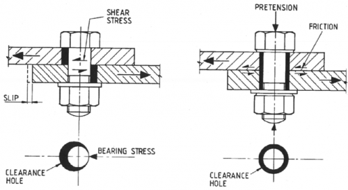

Category A: Bearing Type connections
The design force is transmitted by shear in the bolt shank and bearing between the bolt shank and the connected plies. In order for this mechanism to work, the plies must slip relative to each other. The key advantage of not preloading the bolts are that the bolts only require nominal tightening. However, these types of connections are not to be used in bridges as they have a low fatigue resistance and a tendency to work loose under vibration. These connections may be used in temporary situations.
Category B: Slip-resistant at serviceability limit state
For this category, high strength structural preloaded bolts of property class 8.8 or 10.9 are to be specified. This category is used for connections where a loss of stiffness at ULS is not important. The category is commonly applied to splice connections as these are normally positioned at the points of contra flexure and therefore slip will not shed significant load into the hogging or sagging regions. As well as verifying that there is no slip at SLS, Category B connections need to be checked for bearing resistance and shear resistance at ULS.
Category C: Slip-resistant at ultimate limit state
In this category, preloaded bolts of property class 8.8 or 10.9 are to be specified. This category of connection is required where slip is not acceptable under any circumstances.
In bridge structures, connections are normally designed not to slip at SLS but are allowed to slip into shear and bearing at ULS (Category B); this would normally allow the connection to develop a greater capacity, for the same number of bolts. Some connections however should be designed to ensure there is no slip at ULS (Category C), these would include:
- Bolts in oversized or slotted holes
- Where rigidity is important (i.e. bracing members or to develop U-frame action)
- Hybrid connections using a combination of bolts and welds
[top]Tension connections

Category D: non-preloaded
This connection category should not be used in bridges for the same reasons as Category A.
Category E: preloaded
In this category, preloaded bolts of property class 8.8 or 10.9 are to be specified. This category of connection is not often used but might be used for end plate connections for attaching deck cantilevers or U-frames for example.
[top]Design of bolted connections
Normally each bolted connection will have many bolts and therefore the key consideration in the design is to understand how the design force is shared between the bolts within the group.
When a joint is loaded by a concentric shear only, the force may be assumed to be uniformly distributed amongst the fasteners, provided that the size and class of the fasteners is the same (BS EN 1993-2[1], clause 8.1.9(2)).
For bridge structures, if a moment is applied to a joint, the distribution of internal forces should be linearly proportional to the distance from the centre of rotation (BS EN 1993-2[1], clause 8.1.9(1)). This stipulation is met for a typical girder splice by the practice of calculating the elastic stress in the beam cross-section and then considering the flanges and webs separately.
Web splice bolts need to be designed for the resultant force from the addition of the forces due to the moment carried by the web and the web shear, noting that an additional moment is present due to the shear force times the eccentricity of the bolt group. The force on each bolt in the web splice is as follows:
- Shear force acting vertically, shared equally between the bolt group
- Horizontal force due to the axial force on the web, shared equally among the bolts
- Horizontal force due to the moment on the web and an associated moment due to vertical shear force and the eccentricity of the centroid of the bolt group.
The force on the outermost bolt determines the size of the group.
The flange splice bolts are designed for the force in the flange due to the moment and any axial force in the beam.
For a cross girder connection in a ladder deck, there is normally very little end moment carried by the steel girder and so the splice connection is assumed to transmit the vertical shear and a sagging moment equal to the shear times the distance from the web to the centroid of the bolt group. A cross girder can either be connected using double covers or detailing a single lap between the cross girder web and the main girder stiffener.
In addition, BS EN 1993-1-8[2] specifies that connections need to be checked for block tearing. Block tearing consists of failure in shear along the line of a row of bolts accompanied by a tensile rupture. In practice, this means that the bolt group can be locally ripped out. This failure mechanism may occur where bolt groups are relatively small compared to the area of the connected parts (BS EN 1993-1-8[2], clause 8.1.7.2).
The design of a slip- resistant connection at either SLS or ULS is also affected by the class of friction surface, as described below. It is normal to ensure that the faying surface is a Class A friction surface, i.e. a blast cleaned surface. Further details of the different friction classes are given in BS EN 1090-2[12] and is reproduced below.
| Surface treatment | Class | Slip factor (μ) |
|---|---|---|
| Surfaces blasted with shot or grit with loose rust removed, not pitted | A | 0.50 |
| Surfaces hot-dip galvanized and flash (sweep) blasted and with alkali-zinc silicate paint with a nominal thickness of 60 μm | B | 0.40 |
| Surfaces blasted with shot or grit; a) coated with alkali-zinc silicate paint with a nominal thickness of 60 μm+ b) thermally sprayed with aluminium or zinc or a combination of both to a nominal thickness not exceeding 80 μm |
B | 0.40 |
| Surfaces hot-dip galvanized and flash (sweep) blasted | C | 0.35 |
| Surfaces cleaned by wire brush or flame cleaning, with loose rust removed | C | 0.30 |
| Surfaces as rolled | D | 0.20 |
+See AD 383 & AD 429 for further details.
If the friction surface has any other surface treatment, the slip factors must be established by slip tests, as described in Annex G of BS EN 1090-2[12].
| Property class | Preload (kN) for bolt diameter (mm) | |
|---|---|---|
| 24 | 30 | |
| 8.8 | 198 | 314 |
| 10.9 | 247 | 393 |
Fasteners designed to resist both shear and tension should be designed to clause 3.8 of BS EN 1993-1-8[2], where the tension force is considered to reduce the preload applied to the bolt rather than increasing the force in the bolt.
A worked example of the design of a bolted connection is given in Worked Example 1 in SCI P357.
[top]Detailing
Preloaded bolts are normally used in clearance holes, e.g. M24 bolt in a 26mm hole, but it may be appropriate for oversized holes to be used.
Minimum and maximum bolt spacings and edge distances are given by BS EN 1993-1-8[2], clause 3.5 and Table 3.3, with additional requirements for structures subject to repeated fluctuations of stress that can cause fatigue in BS EN 1993-1-9[13], Table 8.1. (Note that minimum bolt spacing and edge distances are governed by hole diameter and not bolt size.) Guidance on detailing connections is given in Guidance Notes 2.06 and 5.08 and further guidance for bracing and bolted connections is given in Guidance Note 2.03.
[top]Typical girder bolted splice connection
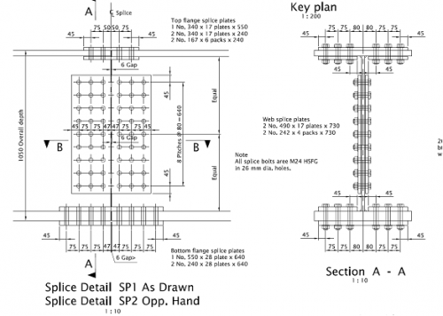

A typical connection is a splice in the main longitudinal beams of a bridge. These should normally be located where a change in the section size is appropriate. In medium span bridges this is often near the points of contra flexure where the bending moments are lower. Splices at points of maximum bending moment are rarely justified as the loss of section in the tension flange through hole deductions will dictate a significant increase in section.
It is good practice to ensure that the cover plates enclose as much of the joint area as possible to improve durability. Cover plates are normally provided on both faces of the flange and the web to make more efficient use of preloaded bolts. Pack plates are used to make up any difference in web or flange plate thickness either side of the joint.
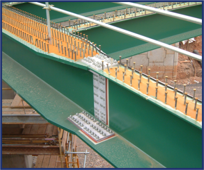

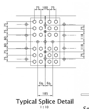

Some longitudinal shear connection may be assumed to be provided by the bolt heads but it is normal practice to ignore the bolt heads and provide shear studs to the top flange cover plate to comply with the maximum longitudinal spacing limitations for shear studs. Careful positioning of the shear studs will be required to ensure that access for bolt tightening is maintained. This will normally limit the shear studs to a single row, though additional shear studs may be provided longitudinally along the line of the web.
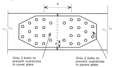
In highly loaded splices, tapered cover plates may be used to provide a more efficient connection detail. The first and last bolt rows of each bolt group are detailed with fewer bolts to improve the stress flow from the flange plate into the cover plate.

[top]Welded connections
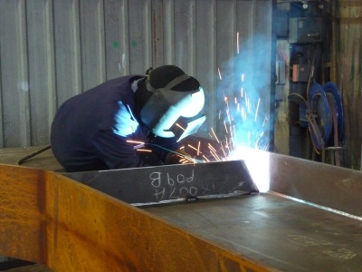

(Image courtesy of Mabey Bridge Ltd.)
Welding is used to join steel components in the fabrication factory and on site. There are several welding processes that are commonly used in bridge steelwork – see Guidance Note 3.04 for further details.
The most two common types of welds found on UK bridge structures are butt welds and fillet welds. Another common weld is a plug welds - these are as they sound, welds used to plug holes.
[top]Butt welds
A butt weld is used for joining two plates together to form a single continuous plate. In this case, the butt welds should be a full penetration butt weld. The full penetration butt weld will normally be specified by the fabricator in flange plates or web plates and normally the bridge designer will not need to design this weld. The design resistance of a full penetration butt weld should be taken as equal to the design resistance of the weaker of the connected parts.
For connections such as a flange to web connection, the complexities of full penetration butt welds should be avoided where possible, as normally designs will only require a particular throat thickness that can be achieved using a partial penetration butt weld or a fillet weld. A partial penetration butt weld should be designed in the same manner as a fillet weld (BS EN 1993-1-8[2], clause 4.5.2(3)).
[top]Fillet welds
A fillet weld is used to join two plates together such as at a lap joint or a 'T'. Fillet welds should not be used where tension would introduce a bending stress that would open the root. The rules for determining the effective throat thickness of a fillet weld are given in BS EN 1993-1-8[2], clause 4.5.2. The normal maximum leg length that can be made in a single pass is 8mm. Therefore if a 12mm fillet weld is required it is normally possible to allow an 8mm deep penetration weld to be used instead as this can be made in a single pass.
Fillet welds may be used for connecting parts where the fusion faces form an angle of between 60° and 120° see clause 4.3.2.1 of BS EN 1993-1-8[2]. Angles smaller than 60° should be considered as partial penetration butt welds. On heavily skewed structures, the welding details may require special consideration.
The effective length of a weld is taken as the length over which the fillet weld is full size. In practice, full size is not achieved at the start and end of a weld and therefore this can be calculated by deducting twice the effective throat thickness from the overall length of the weld.
[top]Design of fillet welds
There are two recognised methods for determining the design resistance of a fillet weld, the directional method or the simplified method.
Directional Method:
In the directional method, the forces transmitted by a unit length of weld are resolved into components parallel to and transverse to the longitudinal axis of the weld, and normal to and transverse to the plane of its throat.
![]()
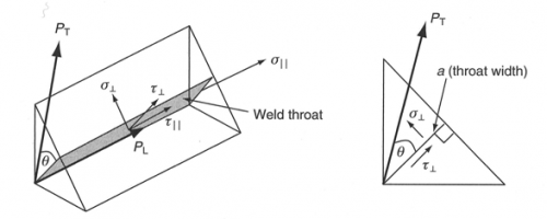

This equation is not practical for design purposes but may be resolved by substituting the resultant longitudinal and transverse forces into the equation using the following resultant expressions for stress:

Simplified method:
The simplified method is an alternative method that requires the designer to calculate the resultant force per unit length on a weld and compare this to the design strength. It is apparent that Fw,Ed is the vector sum of the transverse and longitudinal forces on the weld.

An analysis of the given expressions shows that this is comparable to the derivation for the design expression given for the directional method and identical for weld throats loaded in shear only, where there is transverse load the simplified method will give a conservative result. Hence as the resultant expression (above) for the directional method is easy to apply it is not worth using the simplified method.
[top]Detailing of welded connections
A key issue to consider is access, this is particularly important when members are closely spaced or skew introduces space restrictions. This is where it is sensible to open a dialogue with the fabricator during design to remove some of these issues prior to finalising the design. The cost of inspection, repair and re-inspection of a defective weld is about ten times the cost of getting the weld right in the first place, therefore fabricators will be very keen to work with designers to ensure that welds can be made efficiently.
Shrinkage of the weld will occur and therefore it is important to minimise the resultant distortion. The designer can help the fabricator in this by not over specifying the weld thickness, broadly the bigger the weld, the more heat applied and the more distortion. It is clearly good practice to get the weld throat and leg thicknesses right rather than being overly conservative. Guidance Note 2.07 gives appropriate guidance on specifying welds.
Fatigue is an issue for welded connections and therefore should be considered by the bridge designer. For guidance on the fatigue quality of welded details, see Guidance Note 2.12
General guidance on welded connections in main girders is given in Guidance Note 2.02.
Guidance on the design of welded joints for Celsius®355 and Hybox®355 hollow sections is available from Tata Steel.
[top]Cost factors
Welds need to be specified accurately rather than over specified as the increased costs in preparation, correcting distortion will far outweigh the design effort required. The cost factors for different sizes and types of weld are shown below:
| Size | 
|

|

|
| Cost factor | 1 | 2 | 3 |
| Weld detail | 
|

|

|
| Cost factor | 1 | 4+ | 6+ |
+Not including additional costs for preparation, back-gouging and non-destructive testing for butt welding.
[top]Hybrid connections
Designers should note the limit on ultimate capacity of hybrid connections of both slip resistant bolts acting in friction and welded connections. This is described in clause NA2.26 of the National Annex to BS EN 1993-2:2006[3] as to be taken as no greater than 90% of their combined capacities.
[top]Access for site operations
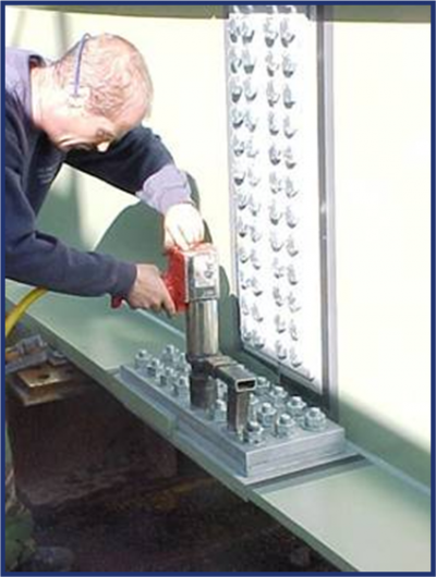
[top]Bolting
In medium span bridges, access for bolting operations can usually be provided with a temporary access platform on from a mobile platform. With larger spans, and where access from beneath is not possible, the provision and removal of access platforms may require significant planning and effort.
- Access for site bolting over a river
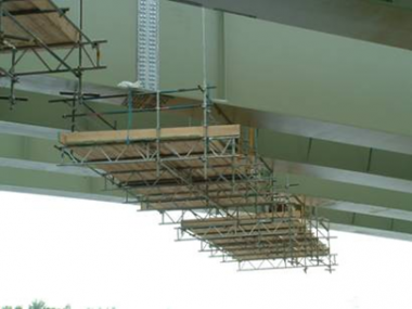
Lagentium Viaduct, A1(M) Darrington to Dishforth
(Image courtesy of Mabey Bridge Ltd.)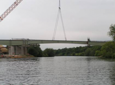
Lagentium Viaduct, A1(M) Darrington to Dishforth
(Image courtesy of Mabey Bridge Ltd.)


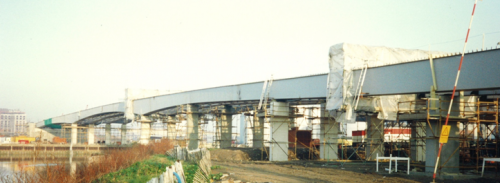
[top]Welding
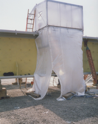

Apart from the provision of access for the welders, which would usually be similar to that for a bolted connection, it is often necessary to protect to welding operation from the weather. This can require quite substantial temporary shelters.

[top]References
- ↑ 1.0 1.1 1.2 BS EN 1993-2:2006. Eurocode 3. Design of Steel Structures. Steel Bridges. BSI
- ↑ 2.00 2.01 2.02 2.03 2.04 2.05 2.06 2.07 2.08 2.09 2.10 2.11 BS EN 1993-1-8:2005. Eurocode 3. Design of Steel Structures. Design of Joints. BSI
- ↑ 3.0 3.1 NA+A1:2012 to BS EN 1993-2:2006. UK National Annex to Eurocode 3. Design of Steel Structures. Steel Bridges. BSI
- ↑ NA to BS EN 1993-1-8:2005. UK National Annex to Eurocode 3. Design of Steel Structures. Design of Joints. BSI
- ↑ BS EN ISO 898-1:2013. Mechanical properties of fasteners made of carbon steel and alloy steel. Bolts, screws and studs with specified property classes. Coarse thread and fine pitch thread. BSI
- ↑ BS EN 14399-1:2015. High-strength structural bolting assemblies for preloading. General requirements. BSI
- ↑ BS EN ISO 4014:2022. Hexagon head bolts. Product grades A and B. BSI
- ↑ BS EN ISO 4016:2022. Hexagon head bolts. Product grade C. BSI
- ↑ BS EN 14399-3:2015. High-strength structural bolting for preloading. System HR. Hexagon bolt and nut assemblies. BSI
- ↑ BS EN 14399-4:2015. High-strength structural bolting assemblies for preloading. System HV. Hexagon bolt and nut assemblies. BSI
- ↑ BS EN 14399-10:2018. High-strength structural bolting assemblies for preloading. System HRC. Bolt and nut assemblies with calibrated preload. BSI
- ↑ 12.0 12.1 BS EN 1090-2:2018. Execution of steel structures and aluminium structures. Technical requirements for steel structures. BSI
- ↑ BS EN 1993-1-9:2005, Eurocode 3. Design of steel structures. Fatigue, BSI
[top]Further reading
- Hendy, C.R.; Murphy, C.J. Designers Guide to BS EN 1993-2 Eurocode 3: Design of steel structures. Part 2 Steel bridges. Thomas Telford Ltd.
- Owens, Graham W.; Cheal, Brian D. (1989) Structural Steelwork Connections. Butterworth & Co.
- Hayward, Alan; Weare, Frank. (1989) Steel Detailer’s Manual. BSP.
[top]Resources
- Iles, D.C. (2010) Composite highway bridge design. (P356 including corrigendum, 2014). SCI
- Iles, D.C. (2010) Composite highway bridge design: Worked examples. (P357 including corrigendum, 2014). SCI
- Hendy, C.R.; Iles, D.C. (2015) Steel Bridge Group: Guidance Notes on best practice in steel bridge construction (6th Issue). (P185). SCI
- Guidance Note 1.09 A comparison of bolted and welded splices
- Guidance Note 2.02 Main girder connections
- Guidance Note 2.03 Bracing and cross girder connections
- Guidance Note 2.06 Connections made with preloaded bolts
- Guidance Note 2.07 Welds – how to specify
- Guidance Note 2.12 Fatigue quality of welded details
- Guidance Note 5.08 Hole sizes and positions for preloaded bolts
- Guidance Note 7.05 Installation of preloaded bolts
- Cosgrove, T. (2004) Tension Control Bolts, Grade S10T in Friction Grip Connections (P324). SCI
- Steel Bridges: A practical approach to design for efficient fabrication and construction. (51/10). BCSA
- Chapter 4: Bolting
- Chapter 5: Welding
- Design of welded joints - Celsius®355 and Hybox®355, 2013, Tata Steel
[top]See also
- Multi-girder composite bridges
- Ladder deck composite bridges
- Weathering steel
- Shear connection in composite bridge beams
- Design for half-through construction
- Fatigue design of bridges
- Bracing systems
- Stiffeners
- Skew bridges
- Design for steel bridge construction
- Fabrication
- Welding
- Accuracy of steel fabrication
- Preloaded bolting