


Construction
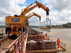
The erection of structural steelwork consists of the assembly of steel components into a frame on site. The processes involve lifting and placing components into position, then connecting them together. Generally this is achieved through bolting but sometimes site welding is used. The assembled frame needs to be aligned before bolting up is completed, and the structure handed over to the principal contractor.
Often the ability to complete these processes safely, quickly and economically is influenced significantly by early decisions made during design long before erection commences. It is important that designers clearly understand the impact that their decisions can have; "buildability" is a valid design objective. In this context, this article draws on the wider advice given in the SCI publication P178 Design for Construction.
Good site co-ordination will facilitate a smooth running project. Adequate access is required by the steelwork contractor for steel transportation, unloading and erection, both on the site as well as on surrounding or adjacent access roads. The provision of well prepared level ground that is able to take the requisite wheel loads is essential. Use of the BCSA Safe Site Handover Certificate will assist in meeting these requirements, thus reducing the risk of accidents and delays due to poor and unsafe site conditions.

(Image courtesy of William Hare Ltd.)
[top]Planning for Construction
To achieve the client’s aspirations on cost, programme and quality, planning for construction should start at the very beginning of the design process. Such planning should consider the construction sequence, the design factors that affect buildability, and site practice in terms of typical erection plant.
[top]Construction sequence
A separate article on Health and Safety includes a section that identifies the design decisions that affect the erection method statement development. In the broader design and planning context, there are three planning factors that affect the buildability of the scheme. These are:
- Practical erection sequence. The location of bracing systems or other means of maintaining structural equilibrium are crucial here.
- Simplicity of assembly. Simply-assembled connections are the main factors here.
- Logical trade sequences. This will affect how development of the master contract programme as the Pre-tender H&S plan metamorphoses into the Construction H&S Plan.
Choosing simply-assembled connections will affect the ability to use site welding. For a joint to be site welded in position, the members will need to be held securely in position such that the fit-up for welding is accurate and rigid. Nearly always this will require both a temporary bolted connection and additional temporary supports. The need to provide these additional facilities often results in site welding being an expensive option.
[top]Design factors
Four design factors to be considered that contribute to buildability are:
- Repetition and standardisation. There are two aspects to standardisation: repetition of the same building type (e.g. the portal shed) and common / standard details for connections.
- Achievable tolerances. If "tight" tolerances are specified (i.e. more restrictive than those in the National Structural Steelwork Specification - NSSS), then special controls will be needed and possibly specially-engineered details.
- Frame type. Here, the primary choice is between braced frames or continuous frames
- Floor systems. For multi-storey frames, the choice of floor system will affect the erection sequence as it determines the stability of the part erected structure.
[top]Site practice
The key parameter when planning for erection is the piece-count. Figures quoted in the SCI case study on Senator House in SCI-P178 are an average 39 pieces lifted and placed per hook per shift and a peak of 60. With a single hook in use and piece weights averaging around 500 kg, this results in an erection rate of around 100 tonnes per week which releases over 1200 sq m of deck per week. This is a relatively heavy piece weight for a medium rise structure, but the area target is dependent on piece count not weight.
The number of pieces erected is dependent on the choice of crane, and its availability for steel erection rather than other construction activity. Cranes vary in their rapidity of movement (hook travel, slewing and jibbing out), and their overall productivity can also be influenced by a wise choice of location within the site footprint. If two crane lifts are necessary the rules for their use in tandem impose a significant penalty in terms of time taken to sling, lift and place loads.
Rates of erection are also influenced by whether special rigging methods and devices can be used for slinging and release of loads.
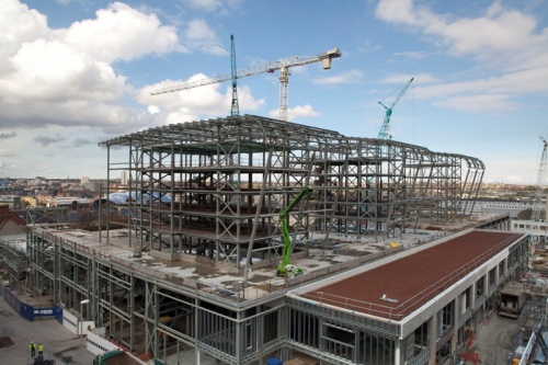
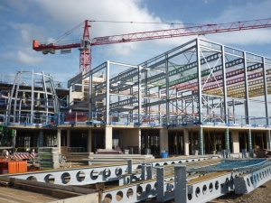
Tower cranes on a major project, Southmead Hospital, Bristol
(Image courtesy of Severfield plc.)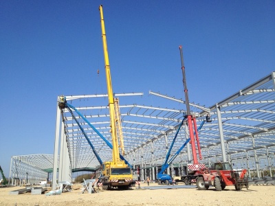
All Terrain cranes on a typical single storey industrial building
(Image courtesy of Severfield (Design & Build) Ltd.)


[top]Steel erection
Steel erection essentially consists of four main tasks:
- Establishing that the foundations are suitable and safe for erection to commence.
- Lifting and placing components into position, generally using cranes but sometimes by jacking. To secure components in place bolted connections will be made, but will not yet be fully tightened. Bracings may similarly not be fully secured.
- Aligning the structure, principally by checking that column bases are lined and level and columns are plumb. Packing in beam-to-column connections may need to be changed to allow column plumb to be adjusted.
- Bolting-up which means completing all the bolted connections to secure and impart rigidity to the frame.
[top]Erection techniques

Cranes and MEWPs (Mobile Elevating Work Platforms) are predominantly used for the erection of structural steelwork for buildings and bridges in the UK, although other techniques are sometimes used for steel bridge construction. Generally, cranes may be divided into two broad categories, mobile and non-mobile. The first category includes truck mounted cranes, crawler cranes and all-terrain cranes, whilst the second category primarily covers tower cranes.
MEWPs are used to access the steelwork during erection, i.e. to bolt-up the pieces being lifted in by the crane. However, the MEWPs themselves can be used both on the ground or on the partly erected steelwork to erect lighter steel elements directly provided special measures are taken to support the MEWP (e.g. steel sections to act as rails supported on the partly erected steel). Also the steelwork will need to be checked that it can support the weight of the MEWP.
[top]Mobile cranes
Normally, truck mounted cranes do not require a back-up crane for site assembly, and require very little set-up time. These two attributes mean that they are suitable for one-off, single day commissions. Their main drawback is that to achieve a high lifting capacity from a light vehicle, a larger footprint is required than for an equivalent crawler crane. The size of the footprint can be increased using outriggers, but good ground conditions are necessary to provide a solid base and ensure adequate stability.
Crawler cranes are more rugged than truck mounted cranes. Ground conditions are therefore less critical. Crawler cranes may travel with suspended loads on site, because they are stable without the use of outriggers. They also have a relatively high lifting capacity. Daily hire is not possible for crawler cranes, because transportation to and from site is expensive, and they require site assembly. They are however more competitive than truck mounted cranes for long periods on site in a relatively fixed location.
All-terrain cranes provide a compromise between the advantages and disadvantages of crawler cranes and truck mounted cranes. They are about 20% more expensive to hire than the latter.
Typical mobile cranes, be they crawlers, truck mounted cranes, or all-terrain, have a rated capacity of around 30 t to 50 t. The largest examples are rated at over l000 t. However, actual lifting capacity is a function of radius, and may be much less than the rated capacity for a given situation. ‘Heavy-lift’ rigs can be used to increase the capacity of large cranes for one-off applications.
A truck mounted crane at Arnside Viaduct, Cumbria
(Image Courtesy of Network Rail and Lindapter)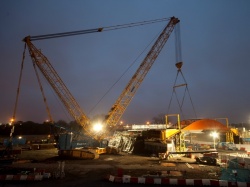
A crawler crane installing L01 Bridge at Olympic Park, London
(Image courtesy of Mabey Bridge Ltd.)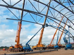
All-terrain cranes at St. George’s Park, National Football Centre, Burton-upon-Trent
(Image courtesy of Tubecon)


[top]Tower cranes

(Image courtesy of William Haley Engineering Ltd.)
Tower cranes must be assembled on site, because of their size, and this operation often requires a second (usually truck mounted) crane. Set-up, and similarly dismantling, is therefore expensive. They also have a relatively slow lifting rate, which means they are only used when site conditions preclude an alternative. A further consideration when specifying a crane is that tower cranes are ‘vulnerable’ to wind loading, which may prevent crane use at times. Their advantages are an ability to lift to greater heights than a mobile, and to lift their rated capacity over a significant proportion of their radius range. Crane geometry means that a tower crane can be erected close to, or within, the building frame. A tower crane may even be tied to the building frame to provide stability as height increases. Alternatively, climbing cranes may be used. These are supported off the steel frame itself.
[top]Typical erection rates
Typical erection rates, and hence the site programme are highly dependent on the number of crane lifts which are needed. To reduce this number, maximum use should be made of pre-assembled units. Alternatively, if crane availability is a problem, the use of steel decking, which can be placed by hand, is preferable to precast concrete units requiring a crane for individual placement. A ‘piece count’ is a useful way for the designer to assess the number of lifts needed and hence the erection duration. An example is given in SCI-P178.
[top]Lining, levelling and plumbing
Lining, levelling and plumbing consists of an interaction between the site engineer using the survey instrument and the erection gang doing the final bolt tightening and shimming. By the progressive use of wedges, jacks, pull-lifts and proprietary pulling devices such as Tirfors, the erection gang persuades the frame to move to a position acceptable to the checking engineer and then bolts it up firmly. Some lack-of-fit is overcome in this process, and some is created. If the latter is adverse, local corrections are made. The team rarely returns to a frame once that it has been checked, plumbed and bolted up.
In the past, there has occasionally been some confusion over the steelwork contractor's responsibilities particularly when loads imposed on the frame after erection (e.g. from flooring and cladding etc.) result in movements that affect the dimensional accuracy of the steelwork. However, BS EN 1090-2[1] clarifies that unless otherwise stated the steelwork contractor is only responsible for the positional accuracy of the steel frame under its self-weight.
The person responsible for the overall stability of the structure should determine whether or not the movements due to such construction loads are significant, and whether there is a need for temporary bracing until the structure is in its final condition. The BCSA publication Allocation of Design Responsibilities in Constructional Steelwork provides a set of easy to use check lists for agreeing responsibilities for the activities associated with the design, fabrication and erection of steelwork.
[top]Tolerances
Tolerances on frame and member geometry are specified in order to ensure that the ‘as built’ frame geometry complies with the designer’s assumptions.
There are two types of tolerance given in BS EN 1090-2[1]; Essential and Functional tolerances. Both are mandatory. The Essential tolerances are those associated with the strength and stability of the structure while Functional tolerances are those associated with fit-up. Also, there are two Classes of functional tolerances. Class 1 is considered appropriate for normal structures. Class 2 is tighter and should only be specified if necessary, e.g. at a critical interface. The National Structural Steelwork Specification (NSSS) specifies Class 1 functional tolerances.
The aim of the Essential tolerances specified in BS EN 1090-2[1] is to ensure that ‘as built’ imperfections are no greater than those assumed in the structural design calculations. Compliance guarantees that frame deviations will not cause secondary forces greater than those allowed for in the design. It also guarantees that lack of fit between the frame members will not be excessive. Limited lack of fit can be accommodated using appropriate packing, without adversely affecting the performance of the connections. Compliance with BS EN 1090-2[1] does not ensure that the frame components will fit together within an envelope which is suitable for the other building components. Secondary systems are required to accommodate cladding systems which may require tighter tolerances that the steelwork for the main structural frame.
The NSSS specifies tolerances needed to satisfy wider conditions than BS EN 1090-2[1]. Quality and buildability of the structure, and requirements for the components to fit together within the specified envelope are addressed. Requirements for specialist following trades such as glazing are not included. The NSSS tolerances reflect the process capabilities of good modern practice, so that specified tolerances are achievable. Use of the NSSS is encouraged.

[top]Interfaces
[top]Structural interfaces
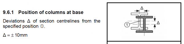
The primary structural interface affecting steel erection is how the frame is to be connected to its supports. UK practice is generally to use holding down bolts that are cast-in-place with some scope for lateral adjustment. Cast-in-place bolts have the advantage that they can contribute to the stability to the steel superstructure immediately – subject to suitable packing and wedging. The problem with casting in bolts without adjustment is principally one for the foundation contractor and not the steel erector.
Column base connection
Using post-drilled fixings requires that the equilibrium of the structure be temporarily secured using, say, guys. This is rarely economic for primary members of the frame but is often used for secondary members such as wind posts for glazing. These can be offered up after the main frame is securely aligned and held in position using the main frame whilst their base fixings are drilled.
The same considerations apply where the steel frame has to be fixed to a concrete core or a masonry wall. Ideally, an adjustable steel attachment plate should be cast into the wall, then surveyed and adjusted such that the subsequent process involves merely as steel-to-steel erection.
In composite construction, the metal deck may need to be assessed for its ability to stabilise the steel members to which it attaches in the temporary condition before the concrete is placed and cured. The "wet concrete" stage is often when the decking is "working hard" to provide support for the dead load which is quite high.
Similarly with precast concrete floor/roof planks, often the most critical conditions arise during the placing of the units. Attention needs to be given to ensure that the asymmetric loading conditions that can arise are carefully controlled.

Concrete being poured onto a composite deck
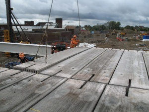
Erecting precast floor planks
(Image courtesy of Severfield (Design & Build) Ltd.)


Finally, primary frame members such as portal rafters may rely on secondary elements such as purlins, ties and knee braces for their stability – even under self-weight only. Occasionally these secondary elements may be timber. In all such cases it is necessary that the erectors have a clear understanding about how many secondary members need to be in place (and how securely they need to be connected) before the crane lifting the primary frame member is released.
[top]Non-structural interfaces


(Image courtesy of Lindapter)
Non-structural interfaces that are common in steel framed buildings include:
- Attachment points and penetrations for M&E services.
- Lift installations.
- Internal fit-out panels including fire protection boards.
- Perimeter and internal masonry walls.
- Metal cladding panels to roof and walls.
- Curtain walling.
- Glazing for façades and skylights.
The most frequent source of difficulty during erection is associated with the fit-up between the erected steelwork and components that require tight tolerances. Common cases are lift installations, "high tech" wall cladding panels and façade glazing.
As mentioned previously, the NSSS tolerances are determined by what is economic within the process capability of the industry and what is necessary for reasons of structural stability. To determine what particular adjustments or clearances might be needed at a support interface between the steel frame and a close-fitting component, an estimate is needed of the variability of the support position offered by the erected steel frame. A separate estimate of variability will be needed based on the details of the supported component and its associated dimensional tolerances. Typically it will be concluded that the supporting cleats need to incorporate adjustability at the attachment interface point.
In some cases there may be architectural or engineering reasons why the range of adjustment might need to be limited. There might be aesthetic restrictions or, in extreme cases, the additional eccentricity of loading could be critical. Perhaps the gaskets between components can only accommodate a limited amount of adjustment. In such cases, working the calculation ‘in reverse’ it is possible to deduce what restrictions might be placed on the permitted deviations for the erected steelwork beyond that given in the NSSS – but there would be costs associated with these tighter tolerances.
For heavy cladding panels and masonry walls, the contribution of deflection under load is often a significant issue. Pre-cambering can be used to compensate for predicted deflection under dead load, but estimates of deflection are not generally exact. The danger might then be to plan the necessary restrictions as described above but to ignore any uncertainty in the estimate of deflection. Assuming the deflection calculation to be fully accurate could then lead to the discovery of this contribution to overall variability only after erection on site, with consequent disruption whilst the solution was sorted out.
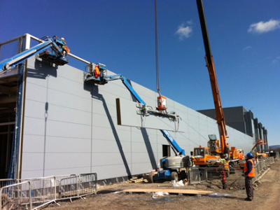

(Image courtesy of Duggan Steel)
[top]Site bolting


(Image courtesy of Lindapter)
Site connections should generally be bolted, as it is faster, less susceptible to poor weather conditions, and has less onerous access and inspection requirements than site welding.
Structural bolting practice (for buildings) in the UK is based predominantly on property class 4.6 and 8.8 non-preloaded bolts to BS EN 15048[2], generally used in 2 mm clearance holes. The recommended option of M20 8.8 fully threaded bolts is readily available. Property class 4.6 bolts are generally used only for fixing lighter components such as purlins or sheeting rails, when 12 mm or 16 mm bolts may be adopted. Generally, only system HR bolts are used in the UK, as recommended in the NSSS
There may be situations, for example a column splice subjected to large load reversals in a braced bay, where the designer considers that joint slip is unacceptable. In these cases property Class 8.8 preloaded bolts to BS EN 14399[3] should be used. Preloaded bolts are also predominantly used on bridgeworks.
Bolts are discussed in the SCI publication Design for Manufacture Guidelines (P150), from which the following points are taken:
- Preloaded bolts should be used ONLY where relative movement of connected parts (slip) is unacceptable, or where there is a possibility of dynamic loading.
- The use of different grade bolts of the same diameter on the same project should be avoided.
- Washers are not required for strength with non-preloaded bolts in normal clearance holes.
- When appropriate, bolts, nuts and washers should be supplied with a corrosion protection coating which does not require further protection on site.
- Bolt lengths should be rationalized.
Common practice is to specify fully threaded bolts, meaning one bolt size can be universally used for a large number of connections. The use of M20, 8.8 fully threaded bolts 60 mm long is recommended, as around 90% of simple connections could be made using such bolts.
Although there are potential minor extra manufacturing costs due to an increase in the average bolt length and a need for more threading, significant overall savings are possible when standard, fully threaded bolts are used:
- Reduced prices due to bulk purchasing
- ‘Just in time' (JIT) purchasing
- No need to compile extensive bolt lists (giving details of bolt types and locations)
- Smaller stock
- Less handling due to reduced sorting
- Faster erection
- Reduced errors (therefore increased safety)
- Reduced wastage.
[top]Site welding
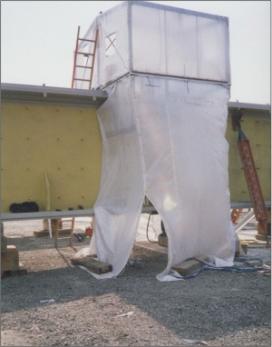

(Image courtesy of Mabey Bridge Ltd.)
Site welding is not normally preferred if a suitable bolted connection is possible. When site welding is adopted, provision must be made for protection against inclement weather, and good access is needed for both welding and inspection. Providing such protection and access may have programme implications, as well as the direct costs involved.
Annex B of the NSSS recommends that site welding is undertaken under the control of a suitably competent welding coordinator on site, appointed by the Responsible Welding Coordinator (RWC). The extent of routine supplementary non-destructive testing (NDT) for site welding is generally the same as factory welding. However, it is recommended that the extent of testing should be 100% for site welds on a new project until the RWC is satisfied that suitable quality levels can be maintained.
[top]Temporary works
Temporary works is more usually associated with the erection of bridges, but the following points may also apply to steel buildings. There are three categories of temporary works, all of which need to be justified and provided or procured in a timely and economic manner:
- Items which are integral with the steel bridge components such as lifting lugs, temporary bracing, and local stiffening. These are best provided in the normal course of fabrication so information is required during the lead-in periods before preparation starts in the works
- Items which affect the substructures or require temporary foundations. These require liaison with the civil works contractor and information in time to meet his construction programme
- Items to be procured or specially fabricated e.g. trestles or launching gear. Sufficient time is required from release of design information for economic procurement
Items of temporary works that are integral to the permanent steelwork can include:
- Bracing members and connections required for stability during erection or deck concreting
- Lifting attachments for individual members, or assemblies (e.g. welded or bolted lifting lugs, drilled holes for eyebolts or cleats)
- Drilled holes for structural restraint prior to fixing bearings
- Steel guides and cleats to aid alignment, fairing and securing of connections for welding
- Drilled holes or welded attachments for securing personnel access, edge protection, and fall arrest systems
- Bolted or welded brackets for subsequent works including falsework
Many of these minor items can be detailed, in consultation with the permanent works designer, so that they need not be removed after use, which will avoid the risk of damage and the requirement for remedial works and additional inspection. Where lifting lugs, for example, cannot be detailed to clear deck reinforcement they can be removed using approved cutting procedures, say 25mm above the flange.
[top]Erection handover
The final objective of the erection process is to handover the frame to following trades in an acceptable condition. The key criterion here is the positional accuracy of the erected frame, and this depends on an understanding of how the erected position of a steel frame is controlled.
A steel framed structure is a very large assembly of a large number of relatively slender and flexible components. Overall accuracies of approximately 1 part in 1000 are sought for plumb and line of the completed structure, using components that may individually be manufactured with greater variability than 1 part in 1000. In addition, deformations such as the flexure of the structure under self-weight of steel affect its actual position. A clear understanding is needed of both the concepts involved and the methods used for control of the erected position of a steel frame.
Within an inspection and test plan, tests undertaken at handover of an erected steel structure could be considered to be final acceptance tests. To be meaningful, all tests require the following to be specified:
- The method of testing
- The location and frequency of tests
- Acceptance criteria
- Actions to be taken if compliance is not achieved.
This is a difficult area in several ways.
Firstly, a dimensional survey is the usual method of testing, but its accuracy is limited by the accuracy of the surveying equipment. Dimensions are only measured to at best 2 mm and often 5 mm, using optical instruments. This limited accuracy means that it may not be possible to achieve, or demonstrate, compliance of the frame.
Secondly, the location and frequency of checking might well represent less than a quarter of all main frame connection points.
Thirdly, the normal procedure for alignment of columns by plumbing-up (see earlier) is not a final acceptance test as such.
Demonstration of compliance using a full three-dimensional survey of the complete structure as a final acceptance test is not practical, because of difficulty, time and expense. Neither is it necessary if the purpose is to ensure the stability of the frame. When tolerances are satisfied over a representative part of the frame, deviations in the rest of the frame can be assumed to be acceptable based on a visual inspection alone.
Tolerances specified in the NSSS for erected steelwork assume that the frame position is checked under the self weight of the steel members alone. Due consideration must also be given to the fact that the frame position will vary according to wind loading, so checks should be made in calm weather conditions. The influence of differential temperatures must also be considered; the NSSS specifies a reference temperature of 20°C.
BCSA has developed sample ‘Handover Certificates’ to formally confirm that the steelwork has been checked for level and alignment etc. and is ready for the installation of the metal decking, and then subsequently the next phase of the construction work.
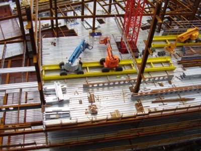
[top]Installation of metal decking


Composite floors, comprising profiled steel decking and insitu concrete, are widely used in steel-framed multi-storey buildings in the UK. They have a proven record of providing an economic solution that can be erected quickly and safely.
The main advantage of using steel decking at the erection stage is that the decking can be used as unpropped permanent formwork when the supporting beams are at not more than 3 m to 3.5 m centres. For greater spans, propping, or a deck with a ‘deep’ profile, is needed. The designer should adopt a framing plan to reflect the fact that the decking is only one way spanning (using a regular grid, with orthogonal beams where possible).
The sheets are laid out as erection progresses up the building. In this way the decking provides a working platform at each floor level, thereby eliminating the need for temporary platforms. It also serves as a crash deck to protect operatives working at lower levels from small objects, and it reduces the effective height at which erectors must work.
For speed of erection, the decking is normally secured to the beams using shot-fired pins. This positive attachment helps to maintain the stability of the steel frame during erection, and laterally restrain the top flanges of the beams during casting of the slab. At the ends of each sheet, the pins should be placed at 300 mm centres, but over intermediate beams the spacing can be increased to 600 mm. If the decking is required to act compositely with the beam, additional attachment is required. This is usually achieved by through-deck welding of the shear connectors.
Guidance is available for the installation of both shallow and deep decking in the BCSA Code of Practice for Metal Decking and Stud Welding, and BCSA have published a series of Metal Deck Health and Safety Guides to help those involved with the laying of metal decking, to reduce the risks associated with manual handling.
- SIG.00 Guidance on manual handling - introduction
- SIG.01 Manual handling survey
- SIG.02 Off site cutting procedures– Case study
- SIG.03 Material loading out and positioning guidelines for Principal / Sub-Contractors
- SIG.04 Manual handling - advice to structural engineers
- SIG.05 Manual handling of decking sheets - reducing the handling risk
Further guidance from BCSA on the installation of metal decking is available in the Metal Decking Good Practice Guide:
- BCSA MDG 01 - Loading and Positioning of Packs
- BCSA MDG 02 - System Edge Protection Installation
- BCSA MDG 03 - Propping Guide
- BCSA MDG 04 - Concrete Pouring
[top]Edge protection
Perimeter edge protection should be positioned to all perimeters, internal voids and phase edges to prevent falls from height. It must be in place before the decking installation begins on each floor or phase.
[top]Methods of fall arrest
In addition to the provision of edge protection at the working level, the working positions for decking operatives require the provision of fall arrest systems. These are three principal systems for providing fall arrest that are used for decking installation:
- Safety netting – Collective and passive fall arrest
- Safety air mats/cushions – collective and passive fall arrest
- Running lines and harnesses – personal and active fall arrest
The choice of system will depend on a number of factors that are specific to individual projects. These will include type of structure (steel/masonry), storey heights, layouts and access methods. However, fall arrest systems that provide collective and passive protection (e.g. nets and air mats/cushions) are preferable in principle, as they protect everyone working within their boundary and do not rely on individual personnel acting to ensure their own protection. Whatever method is used requires careful planning and implementation.
Further information on edge protection and fall arrest systems can be found in publication BCSA Code of Practice for Metal Decking and Stud Welding
[top]Quality management
The steel construction industry and supply chain are able to call upon members of the BCSA and their inherent qualities of competency and professionalism, all demonstrated by among other things, the BCSA Steelwork Contractor membership assessment requirements, the Register of Qualified Steelwork Contractors for Bridgeworks (RQSC), the Steel Construction Certification Scheme (SCCS), CE marking, and the Steel Construction Sustainability Charter (SCSC). Such quality management schemes extend to cover both fabrication and erection.
[top]Health & safety


Under the requirements of the CDM Regulations [4] the principal contractor has overall responsibility for health and safety during construction, and this responsibility is effected through the Construction Health and Safety Plan (now known as the Construction Phase Plan) as he develops the plan for the new building or bridge construction.
The principal safety objectives when erecting steelwork are:
- Safe access and working positions
- Safe lifting and placing of steel components
- Stability and structural adequacy of the part-erected structure
The most serious hazards during steel erection are related to falls from height, either from working positions or while gaining access to them. Other serious hazards are related to structural instability or failure during erection and while handling, transporting, and lifting heavy components. The steelwork contractor's health and safety management system addresses the particular hazards and risks in steel construction as well as the normal range of issues in working on construction sites. His planning for health and safety is systemic to all the preparation for erection through risk assessment, devising safe systems of work and working up the erection method statement.
Cooperation between the steelwork contractor and the principal contractor is essential in the planning and the implementation stages; it is also required by law. The steelwork contractor's safety plan prepared for the project will be complementary to the Construction Health and Safety Plan.
One useful tool to assist in the cooperation between the steelwork and principal contractors, and facilitate the safe erection of steelwork is the BCSA Safe Site Handover Certificate (SSHC). This was specifically developed to provide a consistent approach to safe site conditions and assist clients, principal contractors and steelwork contractors alike to meet their respective responsibilities under health and safety regulations.
Further information regarding the health and safety during construction of steel buildings and bridges are available in the following BCSA publications:
- Safe Site Handover Certificate and Checklist
- Guide to Steel Erection in Windy Conditions
- Code of Practice for Erection of Multi-Storey Buildings
- Guide to the Erection of Steel Bridges
- Code of Practice for Metal Decking and Stud Welding
- Guide to the Management of Site Lifting Operations
- Code of Practice for the Erection of Low Rise Buildings
- Health & Safety on Steel Construction Sites: Guide for Employees
[top]References
- ↑ 1.0 1.1 1.2 1.3 1.4 BS EN 1090-2:2018, Execution of steel structures and aluminium structures. Technical requirements for steel structures, BSI
- ↑ BS EN 15048-1:2016, Non-preloaded structural bolting assemblies. General requirements, BSI
- ↑ BS EN 14399-1:2015, High-strength structural bolting assemblies for preloading. General requirements, BSI
- ↑ Construction (Design and Management) Regulations (CDM) 2015
[top]Resources
- Design for Construction (P178), 1997, SCI
- Design for Manufacture Guidelines (P150), 1995, SCI
- Allocation of Design Responsibilities in Constructional Steelwork, 2007, (Publication no. 45/07), BCSA
- Safe Site Handover Certificate and Checklist, 2008, BCSA
- Guide to Steel Erection in Windy Conditions, 2005, (Publication no. 39/05), BCSA
- Code of Practice for Erection of Multi-Storey Buildings, 2006, (Publication no. 42/06), BCSA
- Guide to the Erection of Steel Bridges, 2005, (Publication no. 38/05), BCSA
- Code of Practice for Metal Decking and Stud Welding, 2014, BCSA
- Guide to the Management of Site Lifting Operations, 2009, (Publication no. 47/09), BCSA
- Code of Practice for the Erection of Low Rise Buildings, 2004, (Publication no. 36/04), BCSA
- Health & Safety on Steel Construction Sites: Guide for Employees, 2009 (Publication no. 48/09), BCSA
- National Structural Steelwork Specification (6th Edition), Publication No. 57/17, BCSA 2017
- Steel Industry Guidance Notes, 2010, BCSA
- SIG.00 Guidance on manual handling - Introduction
- SIG.01 Manual handling survey
- SIG.02 Off site cutting procedures – Case study
- SIG.03 Material loading out and positioning guidelines for Principal / Sub-Contractors
- SIG.04 Manual handling - advice to structural engineers
- SIG.05 Manual handling of decking sheets - reducing the handling risk
- Sample steelwork handover/acceptance certificates, 2017, BCSA:
- Metal Decking Good Practice Guide, 2016, BCSA:
- Steel Buildings, 2003, (Publication No. 35/03), BCSA
- Chapter 10: Bolting
- Chapter 14: Erection
- Chapter 15: Specification and Quality
- Steel Bridges: A practical approach to design for efficient fabrication and construction, 2010, (Publication no. 51/10), BCSA
- Chapter 4 Bolting
- Hendy, C.R.; Iles, D.C. (2015) Steel Bridge Group: Guidance Notes on best practice in steel bridge construction (6th Issue). (P185). SCI
- Guidance Note 4.04 Consideration of alternative construction methods and sequences
- Guidance Note 7.01 Site welding
- Guidance Note 7.02 Temperature effects during construction
- Guidance Note 7.03 Verticality of webs at supports
- Guidance Note 7.04 Trial erection and temporary erection
- Guidance Note 7.05 Installation of preloaded bolts
- Guidance Note 7.08 Method statements
[top]Further reading
- Steel Designer’s Manual (7th Edition), 2011, Chapter 34 - Erection, The Steel Construction Institute.