


Design codes and standards
The Eurocodes are a set of structural design standards, developed by CEN (European Committee for Standardisation) over the last 30 years, to cover the design of all types of structures in steel, concrete, timber, masonry and aluminium. In the UK, they are published by BSI under the designations BS EN 1990 to BS EN 1999; each of these ten Eurocodes is published in several Parts and each Part is accompanied by a National Annex that implements the CEN document and adds certain UK-specific provisions.
Although many previous national standards, including BS 5950[1], were withdrawn by BSI in 2010 they can still be used. This is likely to remain the case for some time.
This article introduces the Eurocode system, sets out the format that is used and explains the relationship between the Eurocodes, their National Annexes and non-contradictory complementary information (NCCI ). It explains that the basis of structural design is set out in BS EN 1990[2] and that this defines the common principles and specifies how design values are to be determined and verified. A brief summary of the various actions (loading) that are defined in EN 1991 is given.
The article introduces the parts of EN 1993 (Eurocode 3) that are required when designing a steel framed building and briefly introduces EN 1994 (Eurocode 4), for composite steel and concrete structures, and EN 1992 (Eurocode 2), which covers the design of the concrete elements in composite structures.
Key issues from the relevant Eurocodes are identified. Much more detail is available in a wide range of guides .
| An introduction to the Eurocodes
with contributions from:
|
[top]Building Regulations
The Governments of the UK and its devolved regions publish documents which provide guidance on the means by which compliance with the Building Regulations in force in that region can be achieved. For structure safety these are: Approved Document A[3] (England); Approved Document A[4] (Wales); Scottish Technical Handbook [5] and Technical Booklet D[6] in Northern Ireland. It should be noted that the English and Welsh Approved Documents have been separate only since 2013. Differences between them are small but one should be aware that they exist. When this article, or any other article on this site, refers to Approved Document A, by default it will be the English version[3].
Approved Document A[3] to the Building Regulations (England) currently references the Eurocodes. It states that: British Standards for structural design based on the Eurocodes were.....implemented by the British Standards Institution on 1st April 2010 and it is these standards with their corresponding UK National Annexes which are now referenced in this Approved Document as practical guidance on meeting Part A requirements.
It further states that: There may be alternative ways of achieving compliance with the requirements and there may be cases where it can be demonstrated that the use of withdrawn standards no longer maintained by the British Standards Institution continues to meet Part A requirements.
The Scottish Technical Handbook-Structures[5], has been updated in a similar way.
- Approved Documents


It is important to recognise that the regulatory system in the UK is such that the Building Regulations themselves merely make high level demands, for example that a structure is safe. Use of the standards cited in Approved Document A[3] is only one way to demonstrate that requirement has been met.
[top]Introduction to Eurocodes
[top]CEN documents
There are ten separate Structural Eurocodes:
- EN 1990 Eurocode: Basis of structural design[2]
- EN 1991 Eurocode 1: Actions on structures[7] [8] [9] [10] [11] [12] [13] [14] [15] [16] [17]
- EN 1992 Eurocode 2: Design of concrete structures [18] [19]
- EN 1993 Eurocode 3: Design of steel structures[20] [21] [22] [23] [24] [25] [26] [27] [28]
- EN 1994 Eurocode 4: Design of composite steel and concrete structures[29] [30]
- EN 1995 Eurocode 5: Design of timber structures
- EN 1996 Eurocode 6: Design of masonry structures
- EN 1997 Eurocode 7: Geotechnical design
- EN 1998 Eurocode 8: Design of structures for earthquake resistance
- EN 1999 Eurocode 9: Design of Aluminium Structures
Each Eurocode comprises a number of 'Parts', which are published as separate documents. Each Part consists of a main body of text, normative annexes, and informative annexes (the 'relevance' of which is decided on a national basis).
The full text of each Eurocode Part is issued initially by CEN (European Committee for Standardisation) in three languages with the above 'EN' designations; national standards bodies may translate the text into other languages but may not make any technical changes. The information given in this text is thus the same for each country in Europe.
The Eurocode text is then provided with a front cover and foreword by each national standards body and published within that country using a designation with the national prefix - for example EN 1990 is published by BSI as BS EN 1990[2]. The text may be followed by a National Annex or a National Annex may be published separately.
The Eurocode Parts contain two distinct types of statement - 'Principles' and 'Application Rules'. The former must be followed, to achieve compliance; the latter are rules that will achieve compliance with the Principles but it is permissible to use alternative design rules, provided that they accord with the Principles (see BS EN 1990[2] 1.4(5)).
The general principle that was adopted in drafting the Eurocodes was that there would be no duplication of Principles or Application Rules. Thus the design basis in BS EN 1990[2] applies irrespective of the construction material or the type of structure.
UK designers should be aware that the Eurocodes use terminology and notation that will be unfamiliar, resulting from the ambition to achieve consistency across Europe.
[top]National Annexes
The National Annex (NA) is an essential document when using a Eurocode Part . Where the opportunity is given in the text of the Eurocode, the National Annex will:
- Specify the value of a factor, to modify limiting values or a formula
- Specify which design method may be used
- State whether an informative annex may be used - such annexes are explicitly identified as being open to national acceptance (or otherwise), and may concern things such as test methods.
Although the NA may specify the value of partial factors to be applied to actions and resistances, in many cases it simply accepts the value recommended in the Eurocode text.
The guidance given in a National Annex applies to structures that are to be constructed within that country. National Annexes are likely to differ between countries within Europe. The National Annexes for the country where the structure is to be constructed should always be consulted in the design of a structure.

Typical cover page of a Eurocode part
Typical cover page of a National Annex
to a Eurocode part


Permission to reproduce extracts from British Standards is granted by the British Standards Institution (BSI). No other use of this material is permitted. British Standards can be obtained in PDF or hard copy formats from the BSI online shop: http://shop.bsigroup.com or by contacting BSI Customer Services for hard copies only: Tel: +44 (0)20 8996 9001, Email: cservices@bsigroup.com
[top]NCCI
The National Annex may give references to publications that contain non-contradictory complementary information (NCCI) that will assist the designer when designing a structure to the Eurocodes. According to CEN rules, a National Annex cannot contain NCCI, but references to NCCI may be given. As the name suggests, any guidance that is referenced in the National Annex must not contradict the principles of the Eurocode.
The Eurocodes omit some design guidance where it is considered to be readily available in text books or other established sources. Publications that contain such design guidance may be referenced in the National Annex as NCCI.
To assist designers, the steel construction sector collated a large amount of the NCCI required for steel design and made it available on a readily searchable website www.steel-ncci.co.uk. Whilst this website is currently still live, and useful for identifying what NCCI is available, the documents themselves are now hosted on SCI’s new ‘Portal’. You do not need to be a member of SCI to access these NCCI documents, but non-members will need to register on that website, wait for a verification email, then login and click the 'STEELBIZ' tab before using the search box to locate the appropriate NCCI document and download it (by clicking the small green cloud alongside the description).
Additionally, BSI has published NCCI guidance in the form of several 'Published Documents' (PDs), e.g. PD 6695-1-10[31]. These documents are only informative and do not have the status of a Standard.
[top]BS EN 1990 Basis of structural design
BS EN 1990[2] can be considered as the 'core' document of the structural Eurocode system as it establishes the principles and requirements for the safety, serviceability and durability of structures. It also describes the basis for structural design and verification. The main sections of BS EN 1990[2] include:
- Requirements
- Principles of limit state design
- Basic variables
- Structural analysis and design assisted by testing
- Verification by the partial safety factor method.
[top]Limit state design
The principles of limit state design (LSD) are set out briefly and the relevant design situations are classified as:
- Persistent - Conditions of normal use
- Transient - Temporary conditions, e.g. during repair
- Accidental - Exceptional conditions applicable to the structure or to its exposure, e.g. to fire, explosion or impact
- Seismic - Conditions applicable to the structure when subjected to seismic events.
Ultimate and serviceability limit states are defined and the requirement that verifications (checks) shall be carried out is stated.
[top]Ultimate limit state
The following ultimate limit states (ULS) are required to be verified:
- EQU - Loss of static equilibrium of the structure or a structural element
- STR - Failure or excessive deformation of a structure or structural element
- GEO - Failure or excessive deformation of the ground where the strengths of soil or rock are significant in providing resistance
- FAT - Fatigue failure of the structure or structural elements.
BS EN 1990[2] gives expressions for the effects for three classes of combination of actions at the ultimate limit state:
- Fundamental combinations (for persistent and transient situations)
- Combinations for accidental situations
- Combinations for seismic situations.
For fundamental combinations, BS EN 1990[2] gives two alternative methods to determine the design value of the effects of combined actions.
The first method is to express the combination of actions as:
![]()
The second method is to give two expressions for the combination of actions; the combination that gives the most onerous value should be used for the design verifications:
![]()
![]()
where:
"+" means "to be combined with"
Σ implies "the combined effect of"
Gk,j represents the characteristic value of the j-th unfavourable permanent action
P is a prestressing action
Qk,1 is the characteristic value of leading variable action ('main accompanying action' in 6.10a)
Qk,i represents the characteristic value of the i-th accompanying variable action (i > 1)
γG, γP, γQ are representations of the factor γF according to the type of action to which they relate
ψ is a factor applied to an accompanying action
ξ is a reduction factor applied to unfavourable permanent actions (in 6.10b)
For the majority of steel elements, the above expressions will simplify, as prestressing actions (P) will not be present. Typical values, from the UK National Annex, are given in the tables below.
| Combination | Permanent actions | Leading variable action | Accompanying variable actions | ||
|---|---|---|---|---|---|
| Unfavourable | Favourable | Main | Others | ||
| 6.10 | 1.35 Gkj | 1.00 Gkj | 1.5 Qk,1 | 1.5ψ0,1Qk,i | |
| 6.10a | 1.35 Gkj | 1.00 Gkj | 1.5ψ0,1Qk,1 | 1.5ψ0,1Qk,i | |
| 6.10b | 0.925×1.35 Gkj | 1.00 Gkj | 1.5 Qk,1 | 1.5ψ0,1Qk,i | |
| Action | ψ0 |
|---|---|
| Imposed loads in buildings, category (see BS EN 1991-1-1) | |
| Category A: domestic, residential areas | 0.7 |
| Category B: office areas | 0.7 |
| Category E: storage areas | 1.0 |
| Category H: Roofs | 0.7 |
| Snow loads on buildings (see BS EN 1991-1-3) | |
| For sites located at altitude H ≤ 1000 m (above sea level) | 0.5 |
| Wind loads on buildings (see BS EN 1991-1-4) | 0.5 |
The National Annex[32] must be consulted for guidance on which method to use. In the UK, the National Annex[32] allows either approach to be used. However, in almost all persistent design situations the use of the second method (the use of expressions 6.10a and 6.10b) will produce lower design values of the effects of actions (and for buildings, 6.10b usually gives the governing value). For the transient design situation during execution, 6.10a is effectively the same as 6.10 (since ψ = 1.0 - see BS EN 1991-1-6[16] clauses A.1.1 and NA 2.18) and thus governs rather than 6.10b.
For building design, Annex A of BS EN 1990[2] gives recommended values of the factors γ, ψ and ξ; for buildings in the UK, the values are given in the National Annex to BS EN 1990[32] , clause NA.2.2.
[top]Serviceability limit state
The serviceability limit state combinations of actions used are:
| Characteristic combination | Irreversible limit state which includes the functioning of the structure, damage to finishes or non structural elements |
| Frequent combination | Reversible limit state |
| Quasi permanent combination | Reversible limit states and long term effects |
The expression for the Characteristic combination of actions given in BS EN 1990[2] for serviceability limit state design is shown below.
![]()
The Frequent and Quasi-permanent combinations are not relevant to steel design in the UK.
The serviceability limits for vertical and horizontal deflections and dynamic effects may be given in the relevant material Eurocode. The UK National Annex to BS EN 1993-1-1[21] gives suggested limits for vertical (see table below) and horizontal deflections due to variable actions only, stating that deflections due to permanent actions need not be verified. With agreement from the Client, different limits may be used for a specific project.
| Cantilevers | Length/180 |
| Beams carrying plaster of brittle finish | Span/360 |
| Other beams (except purlins and sheeting rails) | Span/200 |
| Purlins and sheeting rails | To suit the characteristics of particular cladding |
[top]Eurocode 1 - Actions
This section relates to BS EN 1991 Part 1 for buildings only. Alternative actions should be considered for the design of bridges .
[top]Densities, self-weights and imposed loads for buildings
BS EN 1991-1-1[7] gives design guidance and values of actions to be used when designing buildings and civil engineering works. It contains guidance on:
- Densities of construction and stored materials
- Self-weight of construction works
- Imposed loads for buildings.
The accompanying UK National Annex[8] presents tables containing significantly more occupancy sub-groups than given in the main text of the Eurocode. Some typical values are given in the tables below. The UK National Annex[8] also replaces the expression given for the reduction factor for imposed floor loads and accessible roofs (αA) and the reduction factor for imposed loads from several storeys (αn).
| Element | Typical weight |
|---|---|
| Precast units (spanning 6 m, designed for a 5 kN/m² imposed load) |
3 to 4.5 kN/m² |
| Composite slab, normal concrete (130 mm thick, 2400 kg/m³) |
2.4 to 3.0 kN/m² |
| Composite slab, lightweight concrete (130 mm thick 1400 - 1800 kg/m³) |
1.9 to 2.3 kN/m² |
| Services | 0.25 kN/m² |
| Ceilings | 0.1 kN/m² |
| Steelwork (low rise 2 to 6 storeys) | 35 to 50 kg/m² |
| Steelwork (medium rise 7 to 12 storeys) | 40 to 70 kg/m² |
| Category of loaded area | Specific use | Sub-category | Example | qk kN/m² |
Qk kN |
|---|---|---|---|---|---|
| B | Office areas | B1 | General use other than in B2 | 2.5 | 2.7 |
| B2 | At or below ground level | 3.0 | 2.7 |
[top]Actions on structures exposed to fire
The methods given in BS EN 1991-1-2[9] should be used to determine the thermal and mechanical actions that act on structures exposed to fire. The values of actions determined should be used when carrying out fire engineering design to Part 1-2 of the relevant material Eurocode. The values of actions determined are considered to be accidental actions.
The UK NA[10] gives guidance for temperature analysis and fire models.
For the period of time within which to make the temperature analysis the UK NA[10] refers the designer to the:
- Approved Documents for England and Wales
- Scottish Building Standards Technical Handbooks for Scotland
- Technical Booklet E to the Building Regulations (Northern Ireland) for Northern Ireland.
The UK National Annex[10] specifies that no additional actions need be considered as acting simultaneously with the fire load and that the representative value of the variable action Q1 should be taken as the frequent value (ψ1,1, Q1).
[top]Snow loads
BS EN 1991-1-3[11] gives roof snow load coefficients that are to be used with the characteristic ground snow load maps given in Annex C of that Part of BS EN 1991 to determine design roof snow loads for different roof shapes. The UK National Annex[12] replaces the ground snow load map and some of the roof coefficients for buildings to be constructed in the UK.
[top]Wind actions
The guidance given in BS EN 1991-1-4[13] should be used to determine the wind actions to be considered during the structural design of buildings and civil engineering works. The information given is applicable to the whole or part of a structure, including elements attached to it such as cladding. The values of wind actions are derived from a fundamental value of the basic wind velocity (which is given in the appropriate National Annex), from which a mean wind speed and peak velocity pressure are determined for the particular building; wind pressures and forces are determined using coefficients given in BS EN 1991-1-4[13]. The UK National Annex[14] provides numerous tables and figures for determining values for buildings in the UK.
Guidance to assist structural engineers with the evaluation of wind actions for buildings in the UK is available in SCI-P394, and a Wind loading calculator is also available.
[top]Thermal actions
Where structures are exposed to daily and seasonal climatic changes in temperature, the effects of thermal actions should be accounted for in the design. BS EN 1991-1-5[15] gives principles and general rules that should be used to determine the characteristic values of thermal actions.
[top]Actions during execution of buildings
The values of actions which should be taken into account during the construction of a building or civil engineering works should be obtained from the principles and general rules given in BS EN 1991-1-6[16].
The SCI advisory desk note AD346 gives guidance for determining the value of the actions present during the execution of a steel and concrete composite floor.
[top]Accidental actions

Strategies and rules for safeguarding buildings and other civil engineering works against accidental actions are given in BS EN 1991-1-7[17]. There are no rules for determining specific values of accidental actions caused by external explosions, warfare or terrorist activities, or for verifying the residual stability of structures damaged by seismic action or fire, etc.
Information regarding limiting the effects of a localised failure in buildings from an unspecified cause is given in Annex A of BS EN 1991-1-7[17]. The effects are limited in order to avoid disproportionate collapse of the structure. Annex A includes information relating to:
- Categorisation of consequence classes for buildings
- Provision of horizontal tying and vertical ties
- Design of 'key elements'.
[top]Eurocode 3 - Steel structures
BS EN 1993-1[33] Eurocode 3: Design of steel structures comprises a set of general rules in twelve parts (BS EN 1993-1-1[20] to BS EN 1993-1-12[27]) for all types of steel structure and additional rules in separate Parts for structures other than buildings, e.g. BS EN 1993-2[28] for bridges. When designing a building structure of rolled sections and plate girders, the following parts of BS EN 1993-1[33] will be required.
- BS EN 1993-1-1 General rules and rules for buildings[20]
- BS EN 1993-1-2 Structural fire design[22]
- BS EN 1993-1-5 Plated structural elements[24]
- BS EN 1993-1-8 Design of joints[25]
- BS EN 1993-1-10 Material toughness and through-thickness properties.[26]
For steel and concrete composite structures, Eurocode 3 is referred to by Eurocode 4[34] for the design of the steel elements.
SCI has produced a series of guides covering the application of Eurocode 3, as well as an Introduction (SCI P361) and a Concise Guide (SCI P362). These cover all the essential rules for steel building design in accordance with the UK National Annexes.
[top]General rules and rules for buildings
BS EN 1993-1-1[20] gives generic design rules for steel structures and specific guidance for structural steelwork used in buildings. The main aspects in BS EN 1993-1-1[20] are:
[top]Material properties
The rules in BS EN 1993-1-1[20] relate to structural steel grades S235 to S460 in accordance with BS EN 10025[35], BS EN 10210[36] or BS EN 10219[37] and thus cover all the structural steels likely to be used in buildings. In exceptional circumstances, components might use higher strength grades; BS EN 1993-1-12[27] gives guidance on the use of higher strength steels. For the design of stainless steel components and structures, reference should be made to BS EN 1993-1-4[23].
The UK National Annex[21] states that the nominal yield strength (fy) and ultimate strength (fu) of steel should be obtained from the minimum specified values according to the product standards.
Material requirements for fasteners (bolts) are given in BS EN 1993-1-8[25].
[top]Structural analysis
Section 5.2 of BS EN 1993-1-1[20] gives guidance on global analysis of structures and the structural stability of frames.
Generally, first order elastic global analysis may be used. In some circumstances (depending on member classification) plastic global analysis may be used. Where the internal moments and forces are significantly increased due to deflections, second order effects need to be taken into account, either through magnification of first order effects or by a second order analysis.
[top]Section classification


Permission to reproduce extracts from British Standards is granted by the British Standards Institution (BSI). No other use of this material is permitted. British Standards can be obtained in PDF or hard copy formats from the BSI online shop: http://shop.bsigroup.com or by contacting BSI Customer Services for hard copies only: Tel: +44 (0)20 8996 9001, Email: cservices@bsigroup.com
Four classes of cross section are defined in BS EN 1993-1-1[20] . Each part of a section that is in compression is classified and the class of the whole cross section is deemed to be the highest (least favourable) class of its compression parts.
- Class 1 cross-sections are those which can form a plastic hinge with the rotation capacity required from plastic analysis without reduction of the resistance
- Class 2 cross-sections are those which can develop their plastic moment resistance, but have limited rotation capacity because of local buckling
- Class 3 cross-sections are those in which the stress in the extreme compression fibre of the steel member assuming an elastic distribution of stresses can reach the yield strength, but local buckling is liable to prevent development of the plastic moment resistance
- Class 4 cross-sections are those in which local buckling will occur before the attainment of yield stress in one or more parts of the cross-section.
Table 5.2 of BS EN 1993-1-1[20] gives limits for the width to thickness ratios for the compression parts of a section for each classification.
[top]Cross section resistance
Expressions for determining the cross section resistance in tension, compression, bending and shear for the four classes of sections are given in Section 6.2 of BS EN 1993-1-1[20] . The design values of resistance are expressed as Nt,Rd, Nc,Rd, Vc,Rd and Mc,Rd respectively.
For slender webs, the shear resistance may be limited by shear buckling; for such situations, reference is made to BS EN 1993-1-5[24] Shear buckling is rarely a consideration with hot rolled sections.
[top]Buckling resistance of members
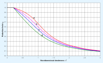

The buckling resistance of a member is determined by applying a reduction factor χ to the yield strength. The value of χ varies depending on the buckling mode, with an appropriate subscript identifying which mode is being considered - for example χLT is the reduction factor for lateral torsional buckling.
The reduction factor χ is a function of the non-dimensional slenderness ![]() , as shown in the figure left. The choice of curve depends on the type of cross-section, and the axis about which buckling will take place. Different curves are used for different buckling modes as explained in SCI P362.
, as shown in the figure left. The choice of curve depends on the type of cross-section, and the axis about which buckling will take place. Different curves are used for different buckling modes as explained in SCI P362.
Member resistances may be readily identified using SCI P363 .
[top]Members in compression
BS EN 1993-1-1[20] presents guidance for checking flexural, torsional and torsional-flexural buckling for members in compression. The latter two modes will not be critical for doubly symmetric I or H sections, or hollow sections.
[top]Members in bending
Laterally unrestrained members in bending about their major axes need to be verified against lateral torsional buckling. Rules are given in Clause 6.3.2 of BS EN 1993-1-1[20].
For uniform members in bending, three approaches may be used:
- Lateral torsional buckling curves - general case
- Lateral torsional buckling curves for rolled sections and equivalent welded sections - this is the recommended approach (SCI P362)
- A simplified assessment method for beams in buildings with discrete lateral restraints to the compression flange.
The guidance given for calculating the beam slenderness for the first two approaches requires the value of the elastic critical moment for lateral torsional buckling (Mcr), but no expressions are given for determining this value. An NCCI method for calculating beam slenderness for rolled I, H and channel sections is given in SCI P362. NCCI (SN003b EN EU) for calculating Mcr is also available.
The third method treats the compression flange and part of the web as a simple compression member.
[top]Members in bending and axial compression
For members subject to bending and axial compression, the criteria given in 6.3.3 of BS EN 1993-1-1[20] must be satisfied.
Interaction factors (kij) used in the verifications may be calculated using either method 1 or 2 given respectively in Annexes A or B of BS EN 1993-1-1[20]. Method 2 is considered to be the simpler of the two methods.
[top]General method for lateral and lateral torsional buckling
The general method given in 6.3.4 of BS EN 1993-1-1[20] should not be confused with the general case for lateral torsional buckling given in 6.3.2.2 of EN 1993-1-1[20]. The general method gives guidance for structural components that are not covered by the guidance given for compression, bending or bending and axial compression members, and is not likely to be used by most building designers.
[top]Serviceability limit states
BS EN 1993-1-1[20] does not give any serviceability limit state limits for dynamic effects, vertical deflections and horizontal deflections. The National Annex for the country where the building is to be constructed should be consulted for guidance. The UK National Annex[21] gives limits for deflections; limits for specific projects should be agreed with the client if they differ from the proposed limits.
[top]Additional guidance for buildings
Informative Annex BB of EN 1993-1-1[20] gives guidance for buckling of structural components in buildings. Guidance is given for:
- Flexural buckling of members in triangulated and lattice structures
- Continuous restraints
- Stable lengths of segments containing plastic hinges for out-of-plane buckling.
[top]Plated structures
The provisions of BS EN 1993-1-5[24] are mainly appropriate to the design of plate girders, where the elements of the cross section are typically more slender. For building frames using hot rolled sections, there is little need to refer to this Part, except for the design of webs subject to transverse forces due to concentrated local forces (commonly referred to as the determination of web bearing and buckling resistances).
Section 6 of BS EN 1993-1-5[24] gives a method for determining the resistance of webs to transverse forces. This method should only be used for rolled I and H sections and welded girders. Although not stated, the method should not be used for structural hollow sections as it gives a single check that combines the web bearing and buckling effects. For structural hollow sections, the NCCI method given in SCI P363 and SCI P374 should be used.
BS EN 1993-1-5[24] also provides guidance on calculating the effective section properties of slender cross sections.
[top]Design of joints

BS EN 1993-1-8[25] gives rules for the design of joints between structural members. Both bolted and welded connections are covered.
Note that a joint is defined as a zone where two or more members are interconnected and a connection is the location where elements meet and is thus the means to transfer forces and moments.
BS EN 1993-1-8[25] gives guidance for the design of joints subject to predominantly static loading. The steel grades covered are S235, S275, S355 and S460. BS EN 1993-1-8[25] uses the so-called component model to identify the resistance of each component making up a joint. Consideration of each of these resistances allows the joint resistance to be identified.
BS EN 1993-1-8[25] classifies joints according to their rotational stiffness as nominally pinned, rigid or semi-rigid and according to their strength as nominally pinned, full-strength or partial-strength. The appropriate type of joint model to be used in global analysis depends on this classification and the method of global analysis.
Although BS EN 1993-1-8[25] provides a method of calculating connection stiffness, a connection may be classified on the basis of previous satisfactory experience. The UK National Annex states that connections designed in accordance with the principles of SCI P358 are nominally pinned; those in accordance with the principles of SCI P398 are rigid.
Detailed design guidance is provided for simple connections in SCI P358 and for moment resisting connections, in SCI P398.
[top]Material toughness and through-thickness properties

Maximum permissible element thicknesses, reference stresses and toughness qualities for different reference temperatures and steel grades are given in Table 2.1 of BS EN 1993-1-10[26]. These should all be considered as part of the material specification.
PD 6695-1-10[31] gives NCCI tables that will enable the determination of maximum permissible thicknesses without considering the individual adjustments and without reference to Table 2.1 in BS EN 1993-1-10[26]. It simplifies the use of BS EN 1993-1-10[26] and is recommended for buildings in the UK. Guidance on selection of an appropriate sub-grade is given in ED007.
However, it should be noted that these design rules were developed for structures subject to fatigue such as bridges and crane supporting structures, and it is acknowledged that their use for buildings where fatigue plays a minor role is extremely safe-sided. SCI publication P419 presents modified steel thickness limits which may be used in buildings where fatigue is not a design consideration. These new limits have been derived using exactly the same approach behind the Eurocode design rules, but crucially reduce the crack growth due to fatigue. Further background is available in a technical article in the September 2017 issue of NSC magazine.
Fracture toughness guidance given in BS EN ISO 1461[38] should be used for hot dip galvanized elements.
[top]Composite structures

When designing a steel and concrete composite building, the following parts of BS EN 1994 Eurocode 4: Design of composite steel and concrete structures will be required:
Within these Parts, reference is made to BS EN 1993 (Eurocode 3) and to BS EN 1992 Eurocode 2: Design of concrete structures, notably to:
SCI has produced guidance on the design of composite floors in accordance with Eurocode 4 (SCI P359).
[top]Eurocode 4 - Composite steel and concrete structures
[top]Material properties
Structural steel
The guidance given in BS EN 1994-1-1[29] relates to structural steel grades up to S460. For steel properties reference is made to BS EN 1993-1-1[20].
Concrete and reinforcement
For structural concrete BS EN 1994-1-1[29] refers to BS EN 1992-1-1[18], although it omits the lowest and highest grades given in that code by only covering:
- Normal weight concrete between C20/25 and C60/75
- Lightweight concrete between LC20/22 and LC60/66.
It also refers to BS EN 1992-1-1[18] for the properties of reinforcing steel. However, it should be noted that BS EN 1994-1-1[29] permits the design value of the modulus of elasticity for reinforcing steel to be taken as equal to that for structural steel given in BS EN 1993-1-1[20], i.e. 210 kN/mm² rather than 200 kN/mm².

The reinforcement industry in the UK has decided to standardise on grade 500C steel.
Shear connectors
BS EN 1994-1-1[29] refers to BS EN ISO 13918[39] , which covers a range of stud diameters from 10 mm to 25 mm and two materials - structural steel and stainless steel.
Profiled steel sheeting (decking)
BS EN 1994-1-1[29] refers to Sections 3.1 and 3.2 of BS EN 1993-1-3[40] for the material properties of profiled steel sheeting.
[top]Structural analysis and stability
First order analysis can be used unless the effects of the deformed geometry significantly modify the structural behaviour, in which case either modified first order effects should be determined or a second order analysis carried out. BS EN 1994-1-1[29] gives rules under four headings for the following types of global analysis:
- Linear elastic analysis, in which allowance is made for cracking of concrete, creep and shrinkage
- Non-linear global analysis, which generally follows the rules for plastic global analysis in BS EN 1993-1-1[20] and takes account of the behaviour of the shear connection
- Linear elastic analysis with limited redistribution, which may be used where second order effects do not need to be considered
- Rigid plastic analysis, for which limitations at plastic hinge locations are given.
Generally, plastic analysis is used as it enables more economic designs. For serviceability limit states, elastic analysis should be used, but where necessary, consideration of concrete cracking should be made.
[top]Section classification
The section classification in BS EN 1993-1-1[20] is adopted for composite sections. Where a steel element is attached to a reinforced concrete element, the classification of the element can, in some cases, be improved. Requirements for ductility of reinforcement in tension are given for Class 1 and Class 2 cross sections.
[top]Modular ratio
For linear elastic analysis, the modular ratio for concrete is required. BS EN 1994-1-1[29] gives an expression that depends on the creep coefficient, as defined in BS EN 1992-1-1[18], and a factor that takes into account the type of loading.
[top]Cross sectional resistance
[top]Bending resistance
The design bending resistance of a composite section may be determined by elastic analysis and non-linear theory for any class of cross section; for Class 1 or Class 2 cross sections, rigid-plastic theory may be used see SCI P359 .
Plastic resistance moments of composite sections may be determined either assuming full interaction between the steel and reinforced concrete or assuming partial shear connection , i.e. when the force transferred to the concrete is limited by resistance of the shear connectors.
[top]Resistance to vertical shear
The resistance of a composite section to vertical shear is generally taken simply as the shear resistance of the structural steel section. Where necessary, the resistance of uncased webs to shear buckling should be determined in accordance with BS EN 1993-1-5[24].
[top]Shear Connection

Rules for the verification of the shear connection in composite beams are given in Section 6.6 of BS EN 1994-1-1[29]. Detailed rules are only given for headed stud connectors. Dimension limits and rules for transverse reinforcement are given. Natural bond between the concrete and steel is ignored.
[top]Design resistance of shear connectors
BS EN 1994-1-1[29] gives the design shear resistance of a headed stud connector as the smaller of the shear resistance of the stud and the crushing strength of the concrete around it. When used with profiled steel sheeting, a reduction factor, based on the geometry of the deck and the height of the stud, is used to reduce the resistance of the shear connectors. Stud connectors have sufficient ductility to develop plastic behaviour, provided that certain limits are observed if there is only partial shear connection.
[top]Partial shear connection
Limitations are given on the use of partial shear connection, i.e. for situations where the design shear resistance over a length of beam is insufficient to develop the full resistance of the composite beam. This will often be a critical design criterion for long-span beams.
[top]Longitudinal shear resistance of concrete slabs
The longitudinal shear resistance of a slab is calculated using the procedure given in BS EN 1992-1-1[18]. However, the shear planes that may be critical and the contributions from the reinforcement or the profiled steel sheeting (if the shear connectors are through-deck welded) are defined in BS EN 1994-1-1[29].
[top]Serviceability limit states
No limits are given for vertical or horizontal deflections. However, Section 7.4 of BS EN 1994-1-1[29] does give details of the minimum reinforcement required to satisfy crack width limits.
[top]Connection design


For composite joints, such as where there is a double-sided beam-to-column joint and the composite slab is continuous, BS EN 1994-1-1[29] provides supplementary rules to those in BS EN 1993‑1‑8[25] to verify the connections. Rules are also given for column web panels in shear or transverse compression when encased in concrete see SCI P213.
[top]CB/203 Design & Execution of Steel Structures
CB/203 is the BSI committee responsible for the British Standards for the design and execution of steel structures, and for the UK input to CEN/TC 250/SC 3 Eurocode 1993 Design of steel structures and Eurocodes related documents. It also mirrors CEN/TC 135 Execution of steel and aluminium structures, and ISO/TC 167 Steel and aluminium structures.
Every 6 months CB/203 publishes a ‘Summary Report to Stakeholders’, which lists the design and execution standards under CB/203 responsibility, the standards due for Enquiry/Vote/Systematic Review, and provides an update on CEN and ISO Activities. The latest version is available below, along with a comments template for the Eurocodes Systematic Review and a more general template for those who use the standards that fall within the scope of CB/203 to comment on their good/bad experiences with the standards and to provide technical comments on them:
- CB/203 Summary Report to Stakeholders, 15 July 2017
- Eurocode Systematic Review Comments Template
- Stakeholder Summary Progress Report Comment Template for CB/203
[top]References
- ↑ BS 5950 Structural use of steelwork in building: Various parts, BSI
- ↑ 2.00 2.01 2.02 2.03 2.04 2.05 2.06 2.07 2.08 2.09 2.10 BS EN 1990:2002+A1:2005. Eurocode: Basis of structural design. BSI
- ↑ 3.0 3.1 3.2 3.3 Approved Document A (Structure) 2004 Edition incorporating 2004, 2010, and 2013 amendments. Department for Communities and Local Government
- ↑ Approved Document A (Structure) 2004 Edition incorporating 2010 amendments (Welsh Government)
- ↑ 5.0 5.1 Building Standards Technical Handbook – Non-domestic buildings 2017, Section 1 – Structure, The Scottish Government
- ↑ Technical Booklet D, Structure, Building Regulations (Northern Ireland) 2012, Department of Finance and Personnel of the Northern Ireland Government, 2012
- ↑ 7.0 7.1 BS EN 1991-1-1: 2002 Eurocode 1. Actions on structures. General actions. Densities, self-weight, imposed loads for buildings, BSI
- ↑ 8.0 8.1 8.2 NA to BS EN 1991-1-1: 2002 UK National Annex to Eurocode 1. Actions on structures. General actions. Densities, self-weight, imposed loads for buildings, BSI
- ↑ 9.0 9.1 BS EN 1991-1-2: 2002 Eurocode 1. Actions on structures. Actions on structures exposed to fire, BSI
- ↑ 10.0 10.1 10.2 10.3 NA to BS EN 1991-1-2: 2002 UK National Annex to Eurocode 1. Actions on structures. General actions. Actions on structures exposed to fire, BSI
- ↑ 11.0 11.1 BS EN 1991-1-3:2003+A1:2015, Eurocode 1. Actions on structures. General actions. Snow loads, BSI
- ↑ 12.0 12.1 NA to BS EN 1991-1-3:2003+A1:2015, UK National Annex to Eurocode 1. Actions on structures. General actions. Snow loads, BSI
- ↑ 13.0 13.1 13.2 BS EN 1991-1-4:2005+A1:2010 Eurocode 1. Actions on structures. General actions. Wind actions, BSI
- ↑ 14.0 14.1 NA to BS EN 1991-1-4:2005+A1:2010, UK National Annex to Eurocode 1. Actions on structures. General actions. Wind actions, British BSI
- ↑ 15.0 15.1 BS EN 1991-1-5:2003, Eurocode 1. Actions on structures. General actions. Thermal actions, BSI
- ↑ 16.0 16.1 16.2 BS EN 1991-1-6: 2005, Eurocode 1. Actions on structures. General actions. Actions during execution, BSI
- ↑ 17.0 17.1 17.2 BS EN 1991-1-7:2006+A1:2014. Eurocode 1: Actions on structures. General actions. Accidental actions. BSI
- ↑ 18.0 18.1 18.2 18.3 18.4 18.5 BS EN 1992-1-1:2004+A1:2014. Eurocode 2: Design of concrete structures. General rules and rules for buildings. BSI
- ↑ 19.0 19.1 BS EN 1992-1-2: 2004 Design of concrete structures. General rules. Structural fire design, BSI
- ↑ 20.00 20.01 20.02 20.03 20.04 20.05 20.06 20.07 20.08 20.09 20.10 20.11 20.12 20.13 20.14 20.15 20.16 20.17 20.18 20.19 20.20 20.21 BS EN 1993-1-1:2005+A1:2014, Eurocode 3: Design of steel structures. General rules and rules for buildings, BSI
- ↑ 21.0 21.1 21.2 21.3 NA to BS EN 1993-1-1:2005+A1:2014, UK National Annex to Eurocode 3: Design of steel structures General rules and rules for buildings, BSI
- ↑ 22.0 22.1 BS EN 1993-1-2: 2005 Eurocode 3. Design of steel structures. General rules. Structural fire design, BSI
- ↑ 23.0 23.1 BS EN 1993-1-4:2006+A1:2015, Eurocode 3. Design of steel structures. General rules. Supplementary rules for stainless steels, BSI
- ↑ 24.0 24.1 24.2 24.3 24.4 24.5 24.6 BS EN 1993-1-5:2006+A2:2019. Eurocode 3: Design of steel structures Plated structural elements. BSI
- ↑ 25.0 25.1 25.2 25.3 25.4 25.5 25.6 25.7 25.8 BS EN 1993-1-8:2005. Eurocode 3: Design of steel structures. Design of joints, BSI
- ↑ 26.0 26.1 26.2 26.3 26.4 BS EN 1993-1-10:2005 Eurocode 3. Design of steel structures. Material toughness and through-thickness properties, BSI
- ↑ 27.0 27.1 27.2 BS EN 1993-1-12: 2007, Eurocode 3. Design of steel structures. Additional rules for the extension of EN 1993 up to steel grades S 700, BSI
- ↑ 28.0 28.1 BS EN 1993-2: 2006 Eurocode 3. Design of steel structures. Steel bridges, BSI
- ↑ 29.00 29.01 29.02 29.03 29.04 29.05 29.06 29.07 29.08 29.09 29.10 29.11 29.12 29.13 BS EN 1994-1-1: 2004 Eurocode 4. Design of composite steel and concrete structures. General rules and rules for buildings. BSI
- ↑ 30.0 30.1 BS EN 1994-1-2:2005+A1:2014, Eurocode 4. Design of composite steel and concrete structures. General rules. Structural fire design, BSI
- ↑ 31.0 31.1 PD 6695-1-10:2009 Recommendations for the design of structures to BS EN 1993-1-10. BSI
- ↑ 32.0 32.1 32.2 NA to BS EN 1990:2002+A1:2005 UK National Annex for Eurocode. Basis of structural design. BSI
- ↑ 33.0 33.1 BS EN 1993 Eurocode 3: Design of steel structures. Various parts, BSI
- ↑ BS EN 1994 Eurocode 4: Design of composite steel and concrete structures. Various parts, BSI
- ↑ BS EN 10025-2: 2019, Hot rolled products of structural steels. Technical delivery conditions for non-alloy structural steels, BSI
- ↑ BS EN 10210-1: 2006, Hot finished structural hollow sections of non-alloy and fine grain steels. Technical delivery requirements, BSI
- ↑ BS EN 10219-1: 2006, Cold formed welded structural hollow sections of non-alloy and fine grain steels. Technical delivery requirements, BSI
- ↑ BS EN ISO 1461: 2009 Hot dip galvanized coatings on fabricated iron and steel articles. Specifications and test methods, BSI
- ↑ BS EN ISO 13918: 2018, Welding. Studs and ceramic ferrules for arc stud welding, BSI
- ↑ BS EN 1993-1-3:2006 Eurocode 3. Design of steel structures. General rules. Supplementary rules for cold-formed members and sheeting, BSI
[top]Further reading
- Steel Designers' Manual 7th Edition. Editors B Davison & G W Owens. The Steel Construction Institute 2012, Chapters 1 and 3
- Eurocode guides to EN1993 and EN1994 from ICE publishing (Thomas Telford).
[top]Resources
- SCI AD346, Design actions during concreting for beams and decking in composite floors, 2010
- NCCI: Elastic critical moment for lateral torsional buckling (SN003b EN EU) SCI
- SCI P359 Composite Design of Steel Framed Buildings, 2011
- SCI P361 Steel Building Design: Introduction to the Eurocodes, 2009
- SCI P362 Steel Building Design: Concise Eurocodes, 2009
- SCI P363 Steel Building Design: Design Data, 2013
A web-based interactive version of the 'Blue Book', is also available. - SCI P374 Steel Building Design: Worked Examples - Hollow Sections, 2009
- SCI P213 Joints in steel construction: Composite connections, 1998
- SCI P358 Joints in Steel Construction - Simple Joints to Eurocode 3, 2014
- SCI P398 Joints in Steel Construction - Moment-resisting Joints to Eurocode 3, 2013
- SCI P394 Wind Actions to BS EN 1991-1-4, SCI, 2013
- SCI ED007 Selection of steel sub-grade in accordance with the Eurocodes, 2012
- SCI P419 Brittle fracture: Selection of steel sub-grade to BS EN 1993-1-10, 2017
- Wind loading calculator
[top]See also
- Steel material properties
- Composite construction
- Modelling and analysis
- Allowing for the effects of deformed frame geometry
- Member design
- Simple connections
- Moment resisting connections
- Structural fire resistance requirements
- Steelwork specification
- Structural robustness