


Design software and tools
A wide range of commercial software is available to aid designers with the efficient and economic design of steel framed buildings and bridges. In addition, the steel sector has developed a number of free software packages and spreadsheet tools to aid designers, which are presented here.
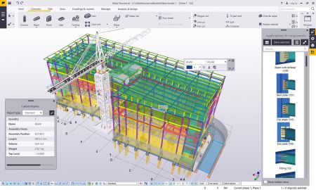

(Image courtesy of Trimble Solutions (UK) Ltd.)
[top]Interactive "Blue Book"
The “Blue Book”, SCI P363, is the essential aid for the design of steelwork. Comprehensive section property data is provided as well as tables of member resistances, which are given for grades S275 and S355. This enables rapid selection of steel members in compression, bending and tension. Tables are also provided for combined bending and compression, web resistance and shear resistance. It also provides:
- Section property data for: hot rolled open sections such as beams, columns, channels and angles; and hollow sections.
- Resistances for ordinary (non pre-loaded) bolts, pre-loaded bolts and welds.
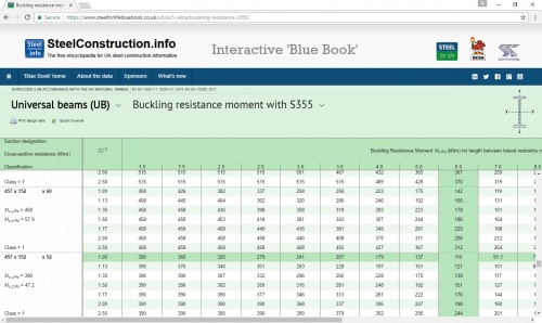
An interactive version of the "Blue Book" is also available that includes design information in accordance with the relevant parts of both the Eurocodes and BS 5950. Produced by the SCI on behalf of Steel for Life, this comprehensive web-hosted eBlue Book covers the full range of both open sections and hollow sections (both hot finished and cold formed), and will not require any software to be installed on the host computer.

Design data is available for:
- Universal beams, universal columns, bearing piles, and parallel flange channels to BS EN 10365[1]
- Structural tees (cut from either universal beams or universal columns) to BS 4-1[2]
- Equal and unequal angles to BS EN 10056[3]
- Hot-finished structural hollow sections to BS EN 10210-2[4]
- Cold-formed structural hollow sections to BS EN 10219-2[5]
Tables are provided for S275, S355 and S460 grades for open sections, S355, S420 and S460 grades for hot-finished hollow sections, and S355 grade for cold-formed hollow sections. Comprehensive design data is also provided for bolts and welds, rolling tolerances are given, and there are comprehensive sets of explanatory notes for both the Eurocodes and BS 5950 data.
Click here to access the freely available Steel for Life Interactive “Blue Book”.
Note:
- Tables of member resistances for HISTAR® grades are available in ArcelorMittal's Orange Book
- Tables of member resistances for hollow sections are also available in Tata Steel’s (tubes only) Blue Book
[top]Member design tools

[top]Compression resistance
This design software calculates the design resistance of beams (UKB), columns (UKC) and hollow sections (both hot finished Celsius® and cold formed Hybox®), subject to axial compression. The design resistance is calculated in accordance with BS EN 1993-1-1[6] and the UK National Annex[7]. The user must select the steel grade, member type, section type and buckling length.
Compression Resistance - UKB, UKC and Hollow Sections
Note - At the time, the software was produced for Universal Beams (Advance® UKB) and Universal Columns (Advance® UKC) manufactured by Tata Steel. The same sections today are simply UB and UC manufactured by British Steel.
[top]Bending resistance
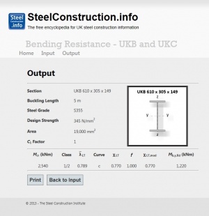
This design software calculates the design resistance of beams (UKB) and columns (UKC) in S275 and S355 subject to bending against the major axis. The design resistance is calculated in accordance with BS EN 1993-1-1[6] and the UK National Annex[7]. The lateral torsional buckling resistance is calculated using the lateral torsional buckling curves for rolled sections. The user must select the steel grade, member type, section type, buckling length and choose the shape of the bending moment diagram by selecting an appropriate C1 factor.
Bending Resistance - UKB and UKC
Note - At the time, the software was produced for Universal Beams (Advance® UKB) and Universal Columns (Advance® UKC) manufactured by Tata Steel. The same sections today are simply UB and UC manufactured by British Steel.
[top]Columns in simple construction
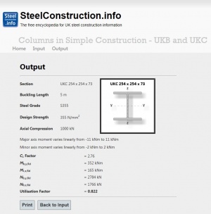

This design software may be used to verify columns in “simple construction” – subject to axial loads and nominal moments from eccentric beam reactions assumed to be 100 mm from the face of the column. The tool covers beams (UKB) and columns (UKC) in S275 and S355 steel. The verification follows the guidance in NCCI: SN048b-EN-GB Verification of columns in simple construction - a simplified interaction criterion.. The scope excludes the verification of class 4 sections. The user must select the steel grade, member type, section size and column length. The tool provides the opportunity to input an axial force (from above), and the design values of the reactions on each face of the column at both ends of the column - these reactions are used to calculate the bending moments in the major and minor axis.
Columns in Simple Construction - UKB and UKC
Note - At the time, the software was produced for Universal Beams (Advance® UKB) and Universal Columns (Advance® UKC) manufactured by Tata Steel. The same sections today are simply UB and UC manufactured by British Steel.
[top]Combined axial compression and bending resistance
This design software provides verification for beams (UKB) and columns (UKC) in S275 and S355 subject to combined bending and axial compression. The calculated interaction between bending and axial compression is verified against BS EN 1993-1-1[6] Expression 6.61 and 6.62 in accordance with the UK National Annex[7]. The interaction factors are determined using Annex B of BS EN 1993-1-1[6]. Identical lengths for major axis buckling, minor axis buckling and lateral torsional buckling are taken. The scope of this tool excludes the verification of class 4 sections. The user must select the steel grade, member type, section type, buckling length and provide the axial compression as well as the maximum and minimum values of major and minor bending moments
Combined Axial Compression and Bending Resistance - UKB and UKC
Note - At the time, the software was produced for Universal Beams (Advance® UKB) and Universal Columns (Advance® UKC) manufactured by Tata Steel. The same sections today are simply UB and UC manufactured by British Steel.
[top]Resistance of beams at elevated temperature
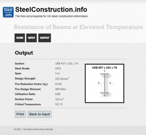

This design software calculates the critical temperature of a beam (UKB) exposed to fire. The software also calculates the time to failure when the beam is unprotected. This software is valid only for restrained beams carrying non-composite precast planks or shallow steel deck floors. The design resistance is calculated in accordance with BS EN 1993-1-1[6] and BS EN 1993-1-2[8], and the UK National Annex[7][9]. The user must select the steel grade, the beam, the loading, the imposed load category and the protection applied. The software assumes that the load on the beam is uniformly distributed.
Resistance of Beams at Elevated Temperature
Note - At the time, the software was produced for Universal Beams (Advance® UKB) manufactured by Tata Steel. The same sections today are simply UB manufactured by British Steel.
[top]Resistance of columns at elevated temperature
This design software calculates the critical temperature of a column (UKC) exposed to fire. The software also calculates the time to failure when the column is unprotected. This software only covers columns in braced frames. The design resistance is calculated in accordance with BS EN 1993-1-1[6] and BS EN 1993-1-2[8], and the UK National Annex[7][9]. The user must select the steel grade, the column, the loading and the imposed load category. The user must also select whether the column is at the top storey or an intermediate storey.
Resistance of Columns at Elevated Temperature
Note - At the time, the software was produced for Universal Columns (Advance® UKC) manufactured by Tata Steel. The same sections today are simply UC manufactured by British Steel.
[top]Composite Beam Checking Tool
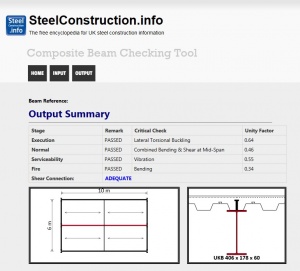

This design software carries out the design of simply supported composite beams to the Eurocodes. It is applicable to secondary beams subject to uniformly distributed loading, or primary beams loaded at midspan or third points. Steel sections may be selected from the range of Beams (UKB) in grade S355. The slab is constructed with metal deck, which may be selected from the ComFlor range, or specified for other metal decks.
Structural steel design is carried out to BS EN 1993-1-1[6], concrete design to BS EN 1992-1-1[10] and composite design to BS EN 1994-1-1[11]. All standards are as implemented by the UK National Annexes[7][12][13]. ULS and SLS checks are carried out for the execution and normal stages. At the execution stage the secondary beam compression flange is assumed to be fully restrained by the metal deck, and the primary beam compression flange is assumed to be restrained at load application points. The design shear connection at the normal stage follows the recommendations of NCCI PN001a-GB and SCI P405, when applicable.
Verification of the beam at elevated temperature is carried out to BS EN 1994-1-2[14]. and its National Annex[15], together with NCCI PN005c-GB which is used to determine temperatures within a concrete slab. The beam may be unprotected or protected; a range of protection types and thicknesses may be selected. If the beam is unprotected, the software reports the time to failure, which may be compared to the required period of fire resistance. If the beam is protected, two results are provided:
- the critical temperature, which may be used to specify the required performance from any protection system.
- the time to failure, which can be compared to the required period of fire resistance.
Note - At the time, the software was produced for Universal Beams (Advance® UKB) manufactured by Tata Steel. The same sections today are simply UB manufactured by British Steel.
[top]Elastic Critical Moment for Lateral Torsional Buckling
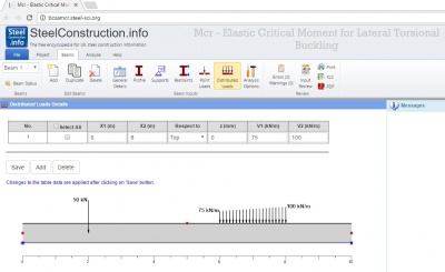

This design software calculates the elastic critical buckling moment for lateral-torsional buckling (Mcr), and the elastic critical load for buckling (Ncr). The scope of the tool includes standard UB and UC sections. Sections may also be defined by dimension, or by property, so the tool can be used to assess fabricated members. The cross section height can also vary linearly along the beam.
A wide range of supports, restraints and loading conditions can be specified. Supports and restraints can be specified at any location along the beam and at a distance from the shear centre, with variable stiffness values. Point, moment and trapezoidal distributed loads can be specified at any location along the beam, and at a distance from the shear centre, to assess destabilising and stabilising loading conditions. Files may be saved and subsequently uploaded from local storage. Reports (summary or detailed) may be printed or exported as XLS and PDF files.
Although the software uses the term ‘Beam’ to refer to the design member, the application of the software is not limited to beams, and it can be used to analyse steel members subjected to bending and axial loading.
A comprehensive help ‘tab’ is provided and it is recommended that first time users refer to this before commencing an analysis.
Mcr - Elastic Critical Moment for Lateral Torsional Buckling
[top]Frame stability
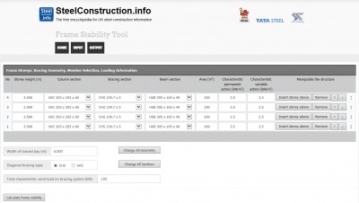

This design software evaluates the frame stability of multi-storey braced frames, in accordance with BS EN 1993-1-1[6]. The parameter αcr is determined using the combination of the Equivalent Horizontal Forces (EHF) and wind loads on the frame, in conjunction with the vertical loads. The calculations are performed for a single vertical bracing system, which is assumed to be a vertical Pratt truss. Beam and column members may be selected from the full range of UKB and UKC’s respectively, and bracing members may be circular or square hollow sections.
From the user-defined characteristic permanent and variable actions, and the floor area associated with the bracing system at each level, the software calculates the EHF. Factors αh and αm are set to 1.0. The characteristic wind load per bracing system is assumed to be uniform over the full height of the bracing system; it is converted to point loads at floor levels in proportion to the storey heights.
Two cases are verified, firstly with imposed load as the leading variable action and secondly with the wind as the leading variable action.
Note - At the time, the software was produced for Universal Beams (Advance® UKB) and Universal Columns (Advance® UKC) manufactured by Tata Steel. The same sections today are simply UB and UC manufactured by British Steel.
[top]Connection design tools
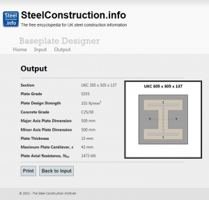

[top]Base plate designer
This design software calculates the axial resistance of a nominally pinned base plate. The column may be a Universal Beam (UKB), Universal Column (UKC) or hollow section (both hot finished Celsius® and cold formed Hybox®). The design resistance is calculated in accordance with BS EN 1993-1-1[6] and the UK National Annex[7]. In addition to selecting the column and the grade of concrete, the user must select the size, thickness and steel grade of the base plate.
Note - At the time, the software was produced for Universal Beams (Advance® UKB) and Universal Columns (Advance® UKC) manufactured by Tata Steel. The same sections today are simply UB and UC manufactured by British Steel.
[top]End plate designer
This design software calculates the vertical shear resistance and tying resistance of partial depth and full depth end plate connections on Universal Beams (UKB). The design resistances are calculated in accordance with BS EN 1993-1-8[16] and the UK National Annex[17], following the procedures in the ‘Green Book’ (P358). Selecting the steel grade and beam size generates a set of parameters for a typical standard end plate connection. These parameters (number of bolt rows, pitch, offset, edge distances, gauge, plate width and thickness) may subsequently be changed and the resistances re-calculated. At any stage, re-selecting the beam will generate the typical connection.
Note - At the time, the software was produced for Universal Beams (Advance® UKB) manufactured by Tata Steel. The same sections today are simply UB manufactured by British Steel.
[top]Fin plate designer
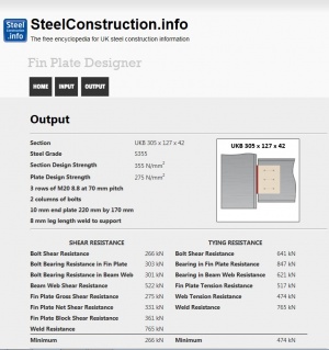

This design software calculates the vertical shear resistance and tying resistance of fin plate connections on Universal Beams (UKB). The design resistances are calculated in accordance with BS EN 1993-1-8[16] and the UK National Annex[17], following the procedures in the ‘Green Book’ (P358). Selecting the steel grade and beam size generates a set of parameters for a typical standard fin plate connection. These parameters (number of bolt rows, pitch, offset, edge distances, gauge, and plate thickness) may subsequently be changed and the resistances re-calculated. At any stage, re-selecting the beam will generate the typical connection.
Note - At the time, the software was produced for Universal Beams (Advance® UKB) manufactured by Tata Steel. The same sections today are simply UB manufactured by British Steel.
[top]Gusset plate designer
This design software may be used to verify the resistance of lapped gusset plate connections subject to compression, typically used where diagonal bracing connects to other members. The gusset plate may be supported on one edge only (sometimes used for lightly loaded roof bracing) or on two edges, which is the common case where vertical bracing intersects at a beam-to-column connection. The design model assumes that the unsupported end of the connection is free to displace laterally, as the bracing member buckles. The eccentricity between the two lapped plates is accounted for in the design model. The resistance of the connection is based on a yield line analysis, with the moment due to eccentricity distributed to the two plates in proportion to their stiffness.
The design model has been validated against tests and Finite Element Analysis for orthodox connections with maximum 20 mm plates, M20 grade 8.8 bolts in square or rectangular patterns and a bracing angle of between 20 ° and 70°. Full details may be found in the ‘Green Book’ (P358), section 8.5.
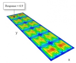
[top]Floor response calculator
This design software allows designers to make an immediate assessment of the dynamic response of a floor solution. The results from this software provide an improved prediction of the dynamic response compared to the ‘manual method’ in SCI P354. The software may be used to examine complete floor plans or part floor plans, comparing alternative beam arrangements.
The software reports the results of approximately 19,000 arrangements of floor grid, loading and bay size, which have been investigated using finite element analysis. The designer must select between a variable action of 2.5 kN/m2 and 5 kN/m2, being typical imposed loads on floors. 0.8 kN/m2 is added to allow for partitions. The designer must also select the arrangement of secondary and primary beams, with typical spans, which depend on the arrangement of the beams. Secondary beams may be placed at mid-span or third points. The pre-set damping ratio of 3% is recommended for furnished floors in normal use.
When a decking profile is selected from the ComFlor range, an appropriate range of slab depths are then available to be selected. Generally, thicker slabs will produce a lower response factor. When selecting the slab depth, solutions which result in a response factor higher than 8 (the limit for a typical office) are highlighted.

The primary and secondary beams are selected automatically from the range of Universal Beams (UKB) in grade S355 as the lightest sections which satisfy strength and deflection requirements; these cannot be changed by the user. The selection of the lightest sections is made to produce the most conservative dynamic response, as stiffer beams will reduce the response.
A visual plot of the response is also provided for both the steady state and transient response. Hovering over the plot shows the response factor. Generally the higher response will be in an end bay, where there is no continuity. The fundamental frequency of the floor is presented on the output screen.
If the actual design differs from the pre-set solutions in the tool, users should note the following:
- Using stiffer beams will reduce the response
- Using thicker slabs, and stiffer beams, will reduce the response
- The gauge of the metal decking has no significant impact on the response factor
- Voids that break the continuity of beam lines will lead to higher response factors
Note - At the time, the software was produced for Universal Beams (Advance® UKB) manufactured by Tata Steel. The same sections today are simply UB manufactured by British Steel.
[top]Carbon footprint tool for buildings
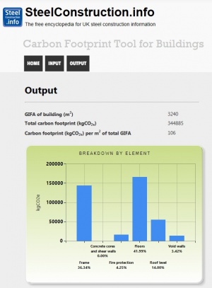

This web tool enables designers of multi-storey buildings to easily estimate the embodied carbon footprint of the superstructure.
There are two ways to use the tool. In ‘Auto generate’ mode, the basic building geometry, structural grid and chosen floor system are used to estimate structural material quantities using algorithms developed by the Steel Construction Institute (SCI) for common structural steel solutions. Alternatively, a user may use the ‘Manual input’ mode to enter the actual material quantities for their building.
Whichever mode is used, appropriate carbon emission factors are then applied to the material quantities to estimate the overall carbon footprint of the building. The results are presented as a single CO2e figure for the building, a CO2e figure per m2 of floor area, and a bar chart illustrating the contributions to the total made by the various elements of the building, i.e. frame, concrete cores, floors, roof, fire protection and void walls.
Carbon Footprint Tool for Buildings


[top]Wind loading calculator
This design software calculates the unfactored design wind loading on walls and roofs of buildings with a rectangular shape in plan. The loading is calculated in accordance with BS EN 1991-1-4[18], the UK National Annex[19], and PD 6688-1-4[20]. Roofs may be flat, monopitch or duopitch. Orography is assumed to be not significant. The user must define the dimensions of the building and provide sufficient geographic data for the evaluation of peak velocity pressure.
[top]FireSoft - concrete filled, hot finished structural hollow section columns in fire and ambient conditions

The UK National Annex to BS EN 1994-1-2[15] prohibits the use of Annex H in determining the capacity of a composite column subject to compression and bending at elevated temperature and makes reference to non-contradictory complementary information (NCCI) in lieu of this.
That NCCI is published as NCCI: PN006a-GB Design guide for concrete filled hot finished structural hollow section columns. This guidance document is consistent with the requirements of BS EN 1994-1-1[11] and BS EN 1994-1-2 [14], including the provisions of each standards' UK National Annex.
Tata Steel and University of Manchester have developed an excel plugin software package called FireSoft that will design a concrete filled hollow section column according to these provisions for fire periods up to 2 hours. It is also suitable for ambient temperature design
The guidance, and therefore FireSoft, is applicable to hot finished structural hollow sections of fine grain steel (BS EN 10210[21][4]) and does not apply to cold formed hollow sections. The guidance and software is applicable to simple construction only.
[top]Acoustic prediction tool
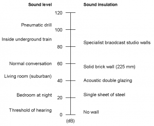

The acoustic prediction tool has been developed to provide designers and architects with a rapid indication of the likely level of acoustic performance for a form of construction selected by the user. The tool will estimate the acoustic insulation provided by different combinations of elements and materials used in the construction of steel wall and floor systems allowing users to carry out a ‘what if’ analysis before embarking on detailed design.
Flooring choices include shallow floors, downstand composite and light steel systems and users can select from a range of floor treatments above and ceiling options below the structural elements. Wall forms involving single or twin studs, with or without acoustic quilting and a range of different boarding options can be selected for analysis.
The values predicted by this tool are only intended to be used for preliminary design purposes because there are many other factors besides specification of the wall or floor format that will affect acoustic performance e.g. junction details, exact specification of products, adjoining construction form and workmanship during construction. The tool is based on empirical interpretation of test data from structures in the residential, health and school sectors to predict the acoustic performance of the user’s chosen arrangement so although these additional factors are not specifically included, their effect is built in to the underlying data allowing a realistic assessment to be made.
Acoustic performance prediction tool
[top]Preliminary bridge design charts


A1, Appleyhead
This easy to use spreadsheet tool created by Atkins for the BCSA and Tata Steel provides initial estimates of flange areas and web thicknesses for typical steel composite bridge cross sections. It is consistent with the latest SCI guidance on composite highway bridge design, and the plate sizes were derived using the Eurocodes and relevant UK National Annexes.
The scope includes simply supported and continuous plate girders for both multi-girder and ladder decks. The spreadsheet tool accounts for the differences between inner and outer girders, and provides both elastic and plastic designs. It is accompanied by a helpful User Manual explaining exactly what the tool is, and how to use it. A series of design charts are also available to facilitate manual calculation if desired.
- Preliminary bridge design charts and spreadsheet tool
- R.Mitchell, D.A.Smith, C.Dolling, Steel–concrete composite bridge design charts for Eurocodes, Proceedings of the ICE - Bridge Engineering, Volume 164, Issue 4, 01 December 2011
- R.Mitchell, D.A.Smith, C.Dolling, Preliminary steel concrete composite bridge design charts for Eurocodes, Atkins Technical Journal 6, Paper 090, June 2011
[top]Bridges carbon calculator
This easy to use spreadsheet tool created by Atkins for the BCSA and Tata Steel calculates the carbon footprint of typical steel composite bridges. It requires a minimum of data and preliminary design quantities to generate an initial result, which can be further refined as more information becomes available. It is accompanied by a helpful User Guide explaining exactly what the tool is, and how to use it.
The results are displayed graphically showing the relative proportions due to construction, maintenance, and traffic delays. The construction element is further sub-divided to show the proportions for the deck, substructures and foundations. This allows a bridge designer to see where the major CO2 burdens are, allowing the focus of design development to be on the big issues in terms of reducing carbon emissions.
- Carbon footprint tool for steel composite highway bridges
- Bridges Carbon Calculator, New Steel Construction magazine, February 2011
- D.A.Smith, P.Spencer, C.Dolling, C.Hendy, Carbon calculator design tool for bridges, Proceedings of the ICE - Bridge Engineering, Volume 168, Issue 3, September 2014
The current version (September 2013) addresses a number of issues identified when the tool was recently used for HS2, and corrects a few other assumptions and errors that were noted during a thorough review by Atkins. The main changes include:
- Correcting an error in calculating all reinforced concrete CO2 values
- Correcting formwork tonnage assumptions
- Correcting the calculation of backfill volume
- Improving the algorithms to estimate the split of concrete volumes between abutment, pier and wingwalls, which now accounts for bridge length
- Improved algorithm for estimating the volume of backfill based on assumed abutment heights, estimated from abutment concrete volumes
- Corrected CO2 values from traffic delay using road closures and full diversions
[top]References
- ↑ BS EN 10365:2017 Hot rolled steel channels, I and H sections. Dimensions and masses. BSI
- ↑ BS 4-1:2005 Structural steel sections. Specification for hot-rolled sections, BSI.
- ↑ BS EN 10056-1:2017 Structural steel equal and unequal leg angles. Dimensions, BSI.
- ↑ 4.0 4.1 BS EN 10210-2:2019 Hot finished steel structural hollow sections. Tolerances, dimensions and sectional properties, BSI.
- ↑ BS EN 10219-2:2019 Cold formed welded steel structural hollow sections. Tolerances, dimensions and sectional properties, BSI.
- ↑ 6.0 6.1 6.2 6.3 6.4 6.5 6.6 6.7 6.8 BS EN 1993-1-1:2005+A1:2014, Eurocode 3: Design of steel structures. General rules and rules for buildings, BSI
- ↑ 7.0 7.1 7.2 7.3 7.4 7.5 7.6 NA+A1:2014 to BS EN 1993-1-1:2005+A1:2014, UK National Annex to Eurocode 3: Design of steel structures General rules and rules for buildings, BSI
- ↑ 8.0 8.1 BS EN 1993-1-2: 2005, Design of steel structures. General rules - structural fire design. BSI
- ↑ 9.0 9.1 NA to BS EN 1993-1-2: 2005, UK National Annex to Eurocode 3: Design of steel structures. General rules - structural fire design. BSI
- ↑ BS EN 1992-1-1:2004+A1:2014 Design of concrete structures. General rules and rules for buildings. BSI
- ↑ 11.0 11.1 BS EN 1994-1-1:2004 Eurocode 4. Design of composite steel and concrete structures. General rules and rules for buildings. BSI
- ↑ NA+A1:2014 to BS EN 1992-1-1:2004+A1:2014, UK National Annex to Eurocode 2. Design of concrete structures. General rules and rules for buildings. BSI
- ↑ NA to BS EN 1994-1-1:2004 UK National Annex to Eurocode 4. Design of composite steel and concrete structures. General rules and rules for buildings. BSI
- ↑ 14.0 14.1 BS EN 1994-1-2:2005+A1:2014, Eurocode 4. Design of composite steel and concrete structures. General rules. Structural fire design. BSI
- ↑ 15.0 15.1 NA to BS EN 1994-1-2:2005 UK National Annex to Eurocode 4. Design of composite steel and concrete structures. General rules. Structural fire design. BSI
- ↑ 16.0 16.1 BS EN 1993-1-8:2005. Eurocode 3: Design of steel structures. Design of joints, BSI
- ↑ 17.0 17.1 NA to BS EN 1993-1-8:2005. UK National Annex to Eurocode 3: Design of steel structures. Design of joints, BSI
- ↑ BS EN 1991-1-4:2005+A1:2010 Eurocode 1. Actions on structures. General actions. Wind actions, BSI
- ↑ NA to BS EN 1991-1-4:2005+A1:2010 UK National Annex to Eurocode 1. Actions on structures. General actions. Wind actions, BSI
- ↑ PD 6688-1-4:2015 Background information to the National Annex to BS EN 1991-1-4 and additional guidance, BSI
- ↑ BS EN 10210-1:2006. Hot finished structural hollow sections of non-alloy and fine grain steels: Technical delivery requirements. BSI