


Facade supports and structural movements
The interface between façade and structure is intrinsic to a clad building. The proper functioning of the connections between them is clearly fundamental to the performance of the cladding and the building as a whole.
This article discusses the support arrangements for different types of façade used on steel-framed buildings, types of brackets and their function, movements of the structure and their impact on the building cladding. It relates to buildings of two or more storeys.

[top]Support arrangements for building envelopes
For practically all different types of façade, the weight of the building envelope and lateral loads applied to it are carried by the primary structure of the building. Low-rise, masonry-clad buildings are an exception, where the masonry envelope may be supported off the ground and only the lateral load is resisted by the building frame. Masonry cladding, rain-screens and insulated render are usually bottom-supported. Precast cladding can be either bottom supported or top-hung. Curtain walling is usually top-hung.
For all types of cladding, the primary structure carries the weight and the support arrangement allows relative movement such that deflections of the primary structure do not impose unintended loads on the cladding system.
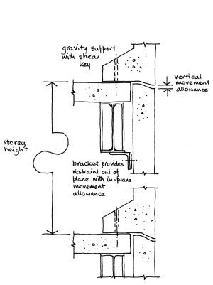
Bottom-supported cladding has to accept deflection of the supporting structure, accommodate vertical movement of the beam above while it provides lateral restraint and allow lateral movement of the building in the plane of the cladding. Top-hung cladding (e.g. curtain walling) has to accept deflection of the supporting structure above, accommodate vertical movement of the structure below while providing lateral restraint and allow lateral movement in the plane of the cladding.

Where the façade element is only restrained laterally by structure, e.g. at the intermediate floor level of a 2-storey mullion, the connection also has to accommodate vertical movement.
Failure to provide sufficient allowance for in-service movements in the connections between façade and structure will inevitably result in load being transferred through elements of the building envelope which they are not designed to carry. This may result in leaks, cracks in brittle elements, failure of connections, buckling of mullions and breakage of glass.
If these potential problems are to be consistently avoided, the building designers should engage with the façade contractor’s designers to understand their requirements and the limitations of their bracketry. Structural elements should be chosen such that movements which the cladding has to accommodate are reasonable and unusual movement requirements are not imposed on the cladding which could result in unexpected costs. These could arise if the movements were such that new transom extrusions had to be designed to accommodate them and the building design team and cost consultant had assumed a conventional solution applied.
It is common for details of building movements to be provided in a report by the structural engineer which can be used by the designers of other building elements. This report has most value if realistic estimates of building movement are to be provided.
[top]Fixings to primary structure
Bottom-supported building envelopes supported at each level, transfer vertical and lateral loads to the primary structure at floor levels as line-loads. Lateral loads are also applied to the underside of the floor above but these loads may be discrete point loads applied through brackets.
Curtain wall gravity loads are normally applied as discrete point loads through brackets suspended from the floor above. Lateral loads are also applied as point loads at floor levels.
Some low-rise buildings are clad in masonry supported at ground level and consequently no gravity loads are applied to the primary frame at the upper floor levels. However, lateral loads are transferred to the primary frame at these levels.
The lateral loads are transferred through horizontal restraint brackets which provide no resistance to vertical movement.
[top]Gravity brackets and other fixings

Gravity loads applied as line loads are either supported directly off the floor slab or a continuous ledge angle is fixed to the edge of the slab. Cast-in channels are often used to retain bolts.
The floor track of a light steel infill wall is usually laid directly on the top of the slab and secured to it by shot-fired fixings which transfer lateral loads. The track can be installed in the correct position relative to the setting-out grid established on the floor.
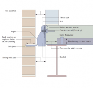
Brick cladding supported on a continuous ledge angle
(Image courtesy of Halfen Deha)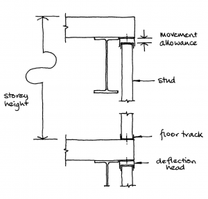
Steel infill wall support


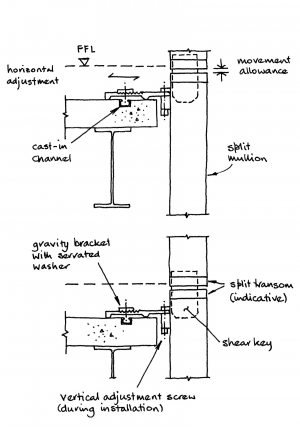
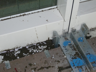
Curtain wall gravity brackets apply point loads and are usually fixed to the top of the slab at the floor edge and hidden beneath a raised-access floor. Alternatively, the brackets may be fixed to the floor edges. Curtain walling manufacturers usually have their own bracket system which can be adjusted in three orthogonal directions.
Horizontal adjustments in-plane and perpendicular to the plane of the curtain wall are achieved by cast-in channels and serrated brackets with slotted holes and serrated washers respectively or other similar means. The length of the cast-in channels and slotted holes provides sufficient adjustment to achieve a true line. The installation tolerances of the cladding may be to within plus or minus 2 mm to maintain the appearance of the joints between panels.
Lateral loads are transferred at the gravity brackets by wedges or Tees in corresponding slots which usually allow vertical screw adjustment.

(Image ©Yuanda Europe)
[top]Restraints
Restraint brackets provide lateral restraint to the building cladding and resist forces normal to the surface (pressure and suction) but allow relative vertical movement between the cladding and the structure.
Light steel infill walls have a channel section head-track fixed toes pointing downward to the soffit of the floor above. The vertical studs are supported laterally by the head-track but a gap between the tops of the studs and the channel web allows vertical deflection of the upper floor relative to the lower one.
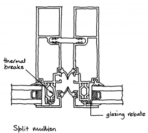
In curtain walling, restraint against out of plane loads is provided at the bottom of a mullion, by a spigot fixed into a cavity in the extrusion which engages with the extrusion below. This provides a means of transferring shear force while allowing axial movement.
Where stick curtain walling mullions are continuous past a floor, the brackets at the intermediate floor levels provide restraint to horizontal loads but allow vertical movements to occur, for example by means of vertical slotted holes.
[top]Impact of NSSS construction tolerances
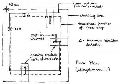
The National Structural Steelwork Specification (NSSS) sets out permitted deviations for erected steelwork. The adjustment necessary to install the cladding to its permitted deviations flows from the NSSS values and dictates the lengths of slotted holes and cast-in channels. The overall plumb of multi-storey columns gives the maximum permitted deviation of the column centre line relative to the column centre at its base. A row of columns at the edge of a floor could all be similarly out of plumb and within the permitted deviation. If it is also assumed that the position of the edge of the floor can vary relative to the position of the columns this also has to be allowed for.
When determining the maximum combined deviation, consideration should be given to whether it is reasonable to assume that the maximum values of the individual permitted deviations can coexist. If this is the case, the maxima should be added. If it is not the case, for example because the deviations are independent and apply to the same element, another means of combination such as the root sum square rule could be used:

Where:
- D is the combined deviation
- di are the individual deviations
- n is the number of individual deviations
If it is assumed to be likely that the maximum deviation of the floor edge between columns can coexist with the maximum out of plumb of the building and that the permitted deviation of the floor edge is the same value as that for beam location in the NSSS, the table shows the adjustment required.
| No of storeys | Plumb | Edge position | Adjustment |
|---|---|---|---|
| 5 storeys of 4.0m | 30 | 5 | ± 35 |
| 10 storeys of 4.0m | 42 | 5 | ± 47 |
| 20 storeys of 4.0m | 60 | 5 | ± 65 |
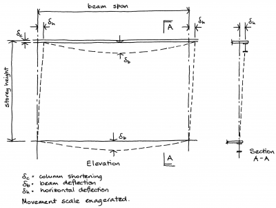
Both inward and outward (plus and minus) adjustment is necessary as illustrated in the diagram

[top]Impact of building movements

(Image ©Arup)
Building movements which affect the cladding can be divided into two classes:
- Movements which occur once during the construction process;
- Movements which occur during the service life of a building.
The first class of movements clearly occurs once only and in general can be assumed not to be reversible.
[top]Vertical movements
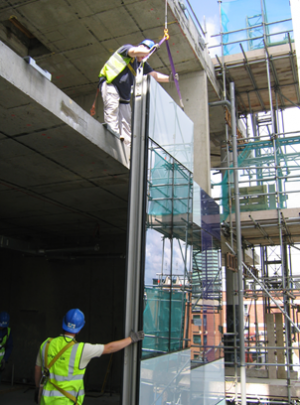
Curtain wall installation takes place after concrete floors have been poured so that cast-in channels are in place. Gravity brackets are fixed to line and approximate level. Installation tolerances to line and plumb are within about 2mm. The first panel is installed and levelled using the adjusting screws in the bracket fixing. Subsequent panels are erected so that the split-mullions engage with each other, and adjusted for level, progressively round the building.
The closing panel is slid vertically down between the panels already erected on either side.
After installation, the cladding has to be capable of accepting building movements and continuing to perform. Movements result from column shortening, beam deflection due to superimposed dead and live loads and thermal effects. Estimated values of movements have been divided into those which occur during construction after cladding installation and those which occur in service and are given in the tables.
| Column shortening due to continuing construction above the installed cladding (will occur in tall buildings) | 0.6 |
| Column shortening due to installation of fit-out elements | 0.3 |
| Permanent deflection of floors due to installation of fit-out elements | 3.2 |
| Column shortening due to live load | 2.2 |
| Deflection of edge beams due to live load | 25 |
| Thermal movement of cladding due to temperature fluctuations | +3.8/-3.3 |
| Thermal movement of frame due to temperature fluctuations (would occur if building is mothballed) | +1.4/-0.7 |

Columns are assumed to be of grade S355 steel with a 4.0m storey height on a 9m grid. Beam deflection figures are based on span/360, the suggested limit given in the UK National Annex to BS EN 1993-1-1[1] for calculated vertical deflections under the characteristic load combinations due to variable loads.
For bottom-supported rigid panels such as precast concrete or masonry, movement joints have to be provided at the top of the panel between it and the structure above to allow beam deflection.
[top]Lateral movements in service
Lateral movement of a building due to wind load results in shear deformation of the cladding panels on the sides of the building parallel to the wind direction. If a lateral displacement of H/500 is assumed, the lateral deflection over a 4.0m storey is 8mm.
[top]Potential effect of beam deflections
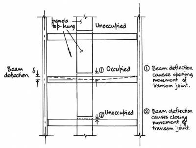

The potential effect of edge beam deflections is explored using unitised curtain walling as an example. Similar effects apply with other cladding systems. In unitised curtain walling, both the interlocking transoms and the mullion joints are required to accommodate the in-service movements of the frame and maintain weather tightness. Where occupied floors are next to unoccupied floors, both opening and closing movements will occur.
Excessive closing movements will result in the transfer of load through cladding elements not designed to sustain it; excessive opening movements could result in the weather tightness of transoms being compromised. Allowances in the curtain wall designed to deal with in-service movement must not be consumed by the accommodation of frame elements which are out of agreed tolerance.
Live load deflections in an edge beam of 25mm can be accommodated by curtain wall panels in two different ways. In unitized curtain wall with split, interlocking mullions where the glazing unit is bonded to the frame with structural silicone, load is transferred to the bracket on one side of a panel as the beam takes up its deflected shape. Adjacent panels slide relative to each other vertically forming steps between adjacent panels.
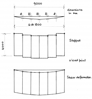

In stick curtain walling and unitized curtain walling where the glazing is not silicone bonded, the panels deform in shear and steps between adjacent panels do not occur. The glazing is usually supported near the vertical edges of the glazing unit. Shear deformation of the curtain wall panel will therefore result in rotation of the glazing to follow the slope of the supporting transom with the potential for glass breakage if contact between the glazing unit and the mullions occurs.
[top]Impact of panel deformation on glazing rebate
The glazing rebate is the channel in which the glazing unit sits and which overlaps the unit all the way round. The gap between the glazing unit and the back of the glazing rebate and the size of overlap accommodate movement of the glass relative to the mullions and transoms framing it.


The magnitude of the relative movement and therefore the theoretically required depth of the glazing rebate depend on the proportions of the glazing unit and the panel deformations.
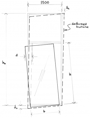
In the diagram (right), d is the minimum clearance between the glazing unit and the frame and the minimum overlap to prevent disengagement and
d = δv(h/b) + δh (h/hs)
For theoretical movements of the magnitudes already considered (maximum relative deflection across a 1500mm wide panel: δv = 14mm and horizontal deflection over one storey: δh = 8mm) and full-height glazing of size 2.6m x 1.3m in a 4.0m storey height:
d = 14 x (2.6/1.3) + 8 x (2.6/4.0) ≈ 33 mm
So the glazing rebate would need to be at least 66 mm deep.
Glazing units 1.3 m square would require a glazing rebate at least 34 mm deep.
In practice, glazing rebates are much smaller than this but glass breakages very rarely occur, suggesting that panel deformations are much smaller too.
[top]Effect of a change of tenancy on theoretical edge beam deflections
An example is given below for a change in tenancy involving new tenant fit-out on one floor of a building using the values for movements during construction and in-service tabulated above. Closing movements have been shown as positive; opening movements have been shown as negative. Beam deflections based on span/1000 have also been tabulated.
These movements occur on emptying and stripping-out the floor and are reversed on refitting and reoccupation. Closing movements due to column shortening under fit-out and live loads of 2.5 mm will already have occurred. The cases shown occur if the maximum thermal movements coincide with the change in occupancy.
| Movement | Opening | Closing | ||
|---|---|---|---|---|
| mm | mm | mm | mm | |
| Beam deflection | L/360 | L/1000 | L/360 | L/1000 |
| Edge beam deflection (services, raised floor, ceiling) | -3.2 | -1.2 | 3.2 | 1.2 |
| Edge beam deflection (live load) | -25.0 | -9.0 | 25.0 | 9.0 |
| Thermal expansion/contraction of cladding | -3.3 | -3.3 | 3.8 | 3.8 |
| Total | -31.5 | -13.5 | 32.0 | 14.0 |
The maximum closing movement relative to installation is 32.0 + 2.5 = 34.5mm for 9m span beams with a deflection limit of span/360. As expected, the edge beam deflection is the dominant component, contributing up to about 82% of the movement for this case.
[top]Movement joints in curtain walling
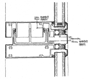

(Image courtesy of Arup)
Split transoms in unitised curtain wall panels must accommodate vertical movement while still maintaining weather tightness. The upper and lower parts of the transoms interlock. Gaskets in pockets provide a seal. As can be seen from the sketch in the figure, excessive closing results in contact between upper and lower transoms which will allow undesirable direct vertical load transfer through the contacting surfaces. Excessive opening results in disengagement of the upper and lower transoms and a direct path from the exterior to the interior of the building.
The maximum deflection that can be accommodated in typical unitised curtain walling panels installed to correct tolerances and clearances is about 15mm as illustrated in the figure (right) and in stick curtain walling systems it is even lower – about 8mm.
Similar issues are relevant to other types of cladding. Mastic sealants are often used in movement joints in masonry and precast cladding. The seals have to remain effective under both opening and closing movements.
[top]Realistic beam deflections
From the discussion above, curtain walling with glazing which is not silicone bonded to the frame is not able to accommodate deformations resulting from the theoretical maximum movements in edge beams due to live loads. It seems clear that a deflection limit of span/360 is not realistic for edge beams supporting cladding and that deflections of this magnitude do not occur in practice. Two possible reasons for this are:
- Actual live loads in buildings are less than specified live loads.
- Nominally simply supported beams achieve sufficient end-fixity to reduce the beam deflection significantly.
It is well known that actual live loads in office buildings are often less than specified live loads and this fact is one reason that buildings clad in curtain walling with similar arrangements to those illustrated apparently experience no problems. It is also known that in practice nominally simply supported beams in conventional construction can achieve a degree of end-fixity which will be sufficient to reduce the beam deflection significantly. Full fixity would result in a mid-span deflection of one fifth of the simply supported deflection; the actual deflection will be somewhere between these two values. SCI publication 183 discusses this issue.
These two effects clearly result in significantly reduced deflections which may be about span/1000 for unitised curtain walling for a 9m span beam. This fact is no-doubt the reason that there have been few reported occasions when excessive deflections of the supporting structure have caused problems with curtain walls.
[top]References
- ↑ NA+A1:2014 to BS EN 1993-1-1:2005+A1:2014. UK National Annex to Eurocode 3: Design of steel structures General rules and rules for buildings, BSI
[top]Resources
- National Structural Steelwork Specification (7th Edition), Publication No. 62/20, BCSA 2020
- Corrigenda - First Revision National Structural Steelwork Specification (7th edition), 2023, (Publication No. 67/23), BCSA
- Commentary (3rd edition) on the National Structural Steelwork Specification for Building Construction (7th edition), 2022, (Publication No. 66/22), BCSA
- SCI P183 Design of Semi-Continuous Braced Frames, 1997