


Infill walling
Infill walling is the generic name given to a panel that is built in between the floors of the primary structural frame of a building and provides support for the cladding system. Infill walls are considered to be non-load bearing, but they resist wind loads applied to the façade and also support their own weight and that of the cladding. Light steel walls using C sections are increasingly used as infill walling within both steel and concrete framed buildings, and have largely replaced masonry or timber alternatives.
An important feature of light steel infill walls is that the size and thickness of the light steel C sections can be varied depending on the height of the façade wall and the wind loads acting on it. Large windows, parapets and other architectural features are made possible. Infill walls are generally installed on site as individual elements that are pre-cut to length but they can be pre-fabricated as large panels with the cladding already attached.
The same components may be used for internal separating walls, but here the main issues are fire resistance and acoustic insulation rather than resistance to loading. A nominal internal pressure is used in the design of internal separating walls.


[top]Types of infill walling
Various forms of construction can be employed to create infill walls that span between floors in steel or concrete buildings. Traditionally, infill walls used masonry or timber, but the modern form of construction uses light steel C sections that span between the floors and around openings. The C sections are placed at a regular spacing depending on the external façade materials, and at a spacing which is also compatible with standard plasterboard and sheathing board sizes.
[top]Light steel framed infill walls
In multi-storey framed construction, it is now common practice to use light steel infill walls to create a rapid dry envelope to support the external cladding. The same form of construction may be used as separating or compartment walls between different parts of the building. The use of light steel infill walls may be applied to steel or concrete framed construction. Light weight, speed and ease of installation are important constructional benefits that have led to the rapid increase in use of this form of construction.
The light steel components used in infill walls consists of C sections and U sections of 75 to 150 mm depth that are cold roll-formed from galvanized steel strip of 1.2 to 3.2 mm thickness specified to BS EN 10346[1]. The galvanizing (zinc layer) provides excellent durability. The C sections are placed at 400 or 600mm spacing and pairs of C sections may be used next to large openings.
Wall panels can be pre-fabricated as storey-high units or, more often, are site assembled from C sections that are delivered cut-to-length. The second approach is often the only solution in renovation applications where tolerances in the original construction have to be accommodated.
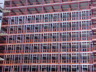
Site assembled light steel walls in a steel framed building
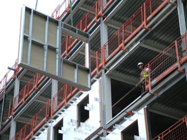
Pre-fabricated light steel infill wall panels in a steel framed building


Infill walls consist of a bottom ‘track’ attached to the floor and a top ‘track’ attached to the underside of the floor above. The top track is a U section and allows for sliding of the vertical studs and height adjustment. This movement is essential in concrete frames, where 2 to 3 mm shortening of the concrete structure per floor can occur over time as well as normal structural movements.
The vertical C sections are designed to span 2.4 to 5m between floors, and to resist wind loads or other loads in bending. The horizontal C sections above and below the windows transfer loads back to the vertical C sections.
One or two layers of ‘fire-resistant’ plasterboard (conforming to BS EN 520[2], Type F) to the internal face provide for up to 90 minutes fire resistance to the light steel infill wall.
[top]Light steel separating walls

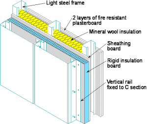
Light steel separating walls use similar components to light steel infill walls and are used to provide acoustic separation and fire compartmentation between occupancies or distinct parts of the building. For both of these functions, double layers walls are generally specified in order to achieve the required acoustic attenuation between occupancies.
The structural loading for internal walls is relatively low and is generally considered to correspond to an internal pressure of 0.5 kN/m². The C sections are generally much thinner than in external walls (typically 0.9mm thick) and gain some benefit of the stiffness of the plasterboard fixed on the outside. Because these walls are non-loading bearing, two layers of plasterboard would generally achieve the required acoustic insulation and 90 minutes fire resistance.
Partitions are not required to have acoustic or fire functions and so are single leaf walls comprising C sections of 55 to 90mm depth, depending on the wall height, with single layers of plasterboard on each side.
[top]Masonry infill walls
Walls constructed from clay bricks or concrete blocks are the traditional form of infill wall construction. However, the use of block-work infill walls has reduced in recent years because it is a messy and time consuming site operation, and requires a large amount of materials handling. From a design point of view, strengthening posts are required next to large window openings, as the masonry is not sufficiently strong to resist the high local wind loads next to these openings.
[top]Concrete infill walls

Concrete infill walls are generally in the form of large precast concrete panels that are storey high and often of a width dictated by the column spacing. These large panels may be top hung or bottom supported. They typically bear onto the floor slab using a boot arrangement, and are bolted back to the structure on the level above or below.
Integral panels may be clad in other materials (typically concrete panels are clad in stone).
Panel weights of approximately 300kg/m² are typical, with panel widths of between 3 and 9m and height of 3.5 to 4.2m. The maximum size of panel is restricted by transport considerations and crane lifting capacity (both on site and at the concrete works). 15 to 20 tonnes are typical maximum weights of precast concrete panels.
[top]Timber framed infill walls
Timber infill walls use standard timber sections of 90 and 140mm depth to span 2.4 to 3.6m between floors and are similar in form to light steel infill walls. Timber sections are cut to length and are placed at 400 mm or 600 mm spacing. The disadvantage of timber in comparison to steel is that it is not as strong and it is not possible to use it in tall walls or in walls with large openings.
[top]Benefits of light steel infill and separating walls
The benefits of light steel infill walls (used externally) and as separating walls (used internally) are:
Speed of construction
Rapid installation of the light steel infill walls creates a weather-tight envelope allowing other activities within the building to proceed much earlier than would be possible with block-work infill walls.
Minimum material use and less handling on site
Fewer materials and less labour to lift and move materials are required, as light steel framing consists of either pre-fabricated wall panels, or assemblies of light weight C sections that are designed to span between the floors. The construction process is ‘dry’ so that shrinkage and other drying-out problems are eliminated. Time savings of over two weeks per floor are readily achievable.
Waste is almost completely eliminated by use of cut-to-length C sections.
Tall walls up to 5 m subject to high wind pressures

Light steel external walls resist wind loads of up to 2kN/m2. These pressures may occur in tall buildings, or at corners due to local wind pressure. Typically 100mm C sections studs are used at 400mm centres, which can span up to 3.6m between floors. In regions of high wind pressure, or for taller walls, 150mm C sections studs may be used. For internal applications, wall heights of up to 7m can be achieved, such as in auditoria.
Light weight
Light steel walls are much lighter and thinner than conventional block-work walls and do not apply heavy line loads to the floor. The typical line load from a light steel wall with lightweight cladding is 2kN/m, which is less than 30% of that of a block-work wall. This is often crucial in refurbishment applications where the quality of the original floor construction is not sufficient to resist heavy loads.
Can be used for a wide range of cladding systems
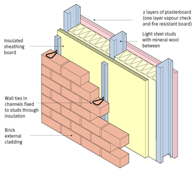
Light steel external walls support lightweight cladding by fixing directly through the insulation to the supporting C sections or indirectly to horizontal rails that are fixed to the C sections. Masonry cladding (brickwork) is relatively heavy and should be ground-supported for walls up to 12m high. For taller walls, it should be supported by the primary frame using stainless steel angles connected to the edge beams. It is tied back to the infill walls using vertical channels in which the wall ties are located. Brick slip systems have also been developed that can be supported vertically and laterally by the infill walls.
Can be re-located in building extensions, etc.
In hospitals, schools and other similar applications, light steel infill walls and separating walls have important benefits by being re-locatable as demand for space changes during the life of the building.
Good fire resistance
Steel is non-combustible unlike timber and fire resistance periods of up to 120 minutes can be achieved using multiple layers of 'fire resistant' plasterboard (conforming to BS EN 520[2], Type F).
Good acoustic performance
Light steel walls can achieve excellent acoustic insulation of 60 dB+ when using double layers of plasterboard and insulating quilt between the studs.
Good thermal properties
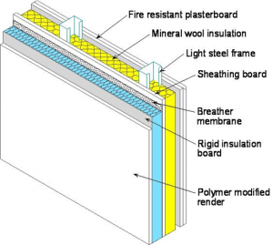
A high level of thermal insulation is provided by a variety of foam insulation boards that attach externally to the studs to create a ‘warm frame’. U-values of less than 0.2W/m²C can be achieved using closed-cell insulation. Brick- or block-work is attached through vertical runners screw fixed to the studs.
Ability to create large openings without wind posts
Large windows up to 3m high and 5m wide can be created using multiple C sections next to the openings, which is not possible with other materials.
[top]Performance requirements for infill walls
The performance requirements for external walls using light steel components include thermal, acoustic, fire resistance, weather-tightness issues and wind resistance, each of which are described in the following sections.
SCI has published ED017 on infill walling and also a series of Technical Information Sheets, one of which was on infill walling ED013. Other publications can be found on the website of the Light Steel Forum.
[top]Thermal performance

In England and Wales, the Government issues and approves Approved Document L (Conservation of fuel and power) to provide practical guidance on ways of complying with the energy efficiency requirements of the Building Regulations. Approved Document L generally referred to as Part L, is in four parts, of which L2A[3] covers new non-domestic buildings. The principal requirements that influence the design of infill walling include:
- Provision of appropriate levels of thermal insulation to reduce heat loss through the wall. Insulation in the form of mineral wool is placed between the C sections and closed cell insulation is placed external to the infill wall as shown below.
- Minimising of thermal bridging by provision of effective continuity of insulation
- Minimising of condensation risk by suitable vapour barriers and by avoiding cold bridging
- Meeting the criterion for maximum air leakage for all new non-domestic buildings over 500m², including the need to measure this using air pressurisation testing.
Thermal transmittance (U-Values)
The amount of heat transmitted through the building envelope per unit area per degree of temperature is termed ‘thermal transmittance’, and it is called the U-value of the building envelope. A U-value of less than 0.22 W/m2K is commonly specified for façade walls to meet the current (2010) requirements of Part L2A[3].
These requirements are for the assembled building envelope and are ‘averaged’ across areas of cladding. The table shows the typical thickness of external insulation in steel infill walls to achieve U-values of 0.18 to 0.25 W/m2K assuming mineral wool is placed between the C sections. This takes account of the local heat loss through the steel sections, which is known as a ‘repeating thermal bridge’ as its effect can be calculated as a part of the wall build up.
Two types of insulation board externally are considered; PIR (Polyisocyanurate) closed cell insulation for brickwork facades and PIR or EPS (Expanded Polystyrene) insulation for insulated render facades. An external insulation thickness of 100mm is generally required to achieve a U-value of 0.2 W/m2K.
Repeating thermal bridging is minimised in light steel construction by placing at least two thirds of the insulation (in terms of its insulating value) externally to the steel elements.
| U-value of wall (Wm-2K-1) | Brickwork facade | Insulated render facade | |||
|---|---|---|---|---|---|
| PIR thickness (mm) | Overall wall depth (mm) | PIR thickness (mm) | EPS thickness (mm) | Overall wall depth (EPS) (mm) | |
| 0.25 | 50 | 315 | 50 | 60 | 210 |
| 0.22 | 80 | 345 | 60 | 80 | 230 |
| 0.20 | 100 | 365 | 80 | 100 | 250 |
| 0.18 | 120 | 385 | 90 | 120 | 270 |
| 0.15 | 150 | 405 | 110 | 150 | 300 |
N.B. All cases assume 100mm C sections with mineral wool insulation between the C sections, and either external PIR (Polyisocyanurate) closed cell insulation or EPS (Expanded Polystyrene) insulation.
Thermal bridging
Thermal bridging that is associated with linear and point effects on the building envelope are known as ’non-repeating thermal bridges’. They are evaluated separately to the U value of the cladding or roofing and are characterised by a ‘psi’ value. This is a measure of the additional heat lost due to thermal bridging as a linear or point value that is added to the general performance of the building envelope.
For light steel infill walls, thermal bridging can occur at the floor slab and at the columns where they cross the line of the wall. However, the amount of thermal bridging is relatively low where the insulation passes outside the edge of the floor slab. Thermal bridging should ideally not add more than 20% to the overall heat loss through the building envelope. Accredited Construction Details (ACDs) are planned for common forms of construction in order to minimise thermal bridging, and ACDs are being developed for light steel infill walls.
Air Leakage
Air leakage can account for over 30% of heat loss from the building and when properly controlled can provide significant benefits in running costs in addition to meeting the regulatory requirements.
Air-tightness testing involves large fans imposing an internal pressure of 50Pa within the building. The quantity of air moving through the fan creates the imposed pressure difference on the building envelope. From this the air leakage rate can be calculated. There are no specific requirements for control of air leakage in most types of buildings, but an air movement of 10 m3/m2/hour (at a test pressure of 50Pa) is typical of most modern buildings. Steel infill walls with external sheathing boards should achieve an air tightness of less than 7 m3/m2/hour. Actual air infiltration rates under normal conditions are only about 5% of the test value, depending on the size of the building and its use. For highly sealed buildings, such as laboratories, fresh air quality should be maintained by suitable ventilation of cleaned air.
Control of condensation
Condensation is a phenomenon where warm moist air condenses on cold surfaces. This effect is minimised by ensuring that cold spots on the internal surface of the building are within limits (normally 10% of the temperature of the rest of the wall). Where there is a risk of condensation within the cladding itself, a vapour tight membrane may be placed on the inside of the building. This should be supplemented by effective and controlled ventilation of the internal space. An infill wall can be installed with foil-backed plasterboard or with a separate membrane in rooms with a high humidity environment.
[top]Acoustic performance
Regulations do not require attenuation of external noise sources but this may be required when building next to busy roads, railway lines, etc. Indicative acoustic performance values for various types of external wall arrangements are shown.
| Description | Weighted sound reduction index, Rw (dB) |
|---|---|
| Solid wall (225 mm brickwork and plaster) | ~ 55 |
| Solid light weight blockwork (100 mm block and plaster) | ~ 43 |
| Basic light steel wall with its external insulation | ~ 45 |
| Light steel wall with brickwork outer leaf | ~ 60 |
| Insulated render on light steel wall | ~ 49 |
| Insulated render on light steel wall with resilient bars | ~ 53 |
| Ventilated rain-screen on light steel wall | ~ 45 |
| Insulated façade panel on light steel wall | ~ 44 |
| Built-up cladding system (120 mm mineral wool) | ~ 40 |
| Built-up cladding system (180 mm mineral wool) | ~ 45 |
Where higher levels of acoustic insulation are required, the internal plasterboard lining can be upgraded, e.g. by using sound insulating boards rather standard wall board or by increasing the number of layers.
[top]Fire resistance
For external walls and compartment walls, Approved Document B[4] (England) states that the relevant period of fire resistance depends on the use, height and size of the building. Where there is a danger that failure of the external wall could lead to fire spread to adjoining buildings (a boundary condition), the wall has to satisfy fire resistance requirements; this may influence the type of cladding that can be used. In such case, a brickwork external leaf that is laterally supported by the light steel infill wall may be preferred.
Two layers of 'fire resistant' plasterboard conforming to (BS EN 520[2], Type F) are sufficient to provide at least 60 minutes fire resistance for the infill wall and to prevent an internal fire extending outside the boundary of the building.
The Government has recently introduced revised regulations concerning the fire performance of external wall systems for buildings more than 18m high (12m in Scotland). This is entitled ‘AMENDMENTS TO REGULATION 7 OF THE BUILDING REGULATIONS 2010 – MATERIALS AND WORKMANSHIP 7’.
Amended regulation 7(2) sets requirements in respect of external walls and specified attachments. This applies to any building with a storey at least 18m above ground level and which contains one or more dwellings; an institution; or a room for residential purposes (excluding any room in a hostel, hotel or a boarding house). This includes student accommodation, care homes, sheltered housing, hospitals and dormitories in boarding schools.
The requirement in amended regulation 7(2) is limited to materials achieving European Class A2-s1, d0 or Class A1 when classified in accordance with BS EN 13501-1[5]. Materials achieving limited combustibility cannot be deemed to meet the requirement using an alternative classification method. Amended regulation 7(3) provides an exemption for certain components found in external walls and specified attachments.
Definitions of external walls and specified attachments have been added and these definitions include any parts of the external wall as well as certain attachments to the external wall (balconies, solar panels and sun shading).
A Consultation document was produced on the proposed amendments to the Building Regulations and the revisions to Part B are presented in a document entitled ‘Amendments to the Approved Documents’, December 2018
The main implication for guidance on infill walls for buildings of more than 6 storeys is that insulation systems that do not satisfy the above requirement are not permitted. Substitute insulation materials, such as stone-wool, do not have such a low thermal conductivity as organic insulation materials and so insulation thicknesses would have to increase to satisfy the same U-value of the wall system.
[top]Weather resistance
Weather resistance concerns the creation and maintenance of a building envelope to resist the penetration of water, and particularly wind-driven rain, from the outside to the inside of the building. It also concerns levels of thermal insulation, hygroscopic performance and appropriate levels of airtightness, which are all within the scope of the Building Regulations. This links to Part L: Conservation of fuel and power and Part F: Ventilation and increasingly to Part B: Fire safety.
Part C of the Building Regulations and its Approved Document[6] 'Site preparation and resistance to contaminates and moisture' presents information on the performance requirements and the design of external walls. This is presented in Section 5.12 onwards in Approved Document C[6].
The exposure of external walls to wind driven rain is also dependent on the geographic region that is classified as having ‘sheltered’ to ‘very severe’ exposure in accordance with BS 8104[7]. Many parts of the UK fall under the ‘moderate‘ or ‘severe’ exposure zones. Table 4 of Approved Document C[6] gives the minimum width of cavity for the different exposure zones and cladding materials. BS 5628-3[8] describes the factors affecting rain penetration in cavity walls.
For curtain walling systems, the forms of construction are defined in BS EN 13830 [9]. The Centre for Window and Cladding Technology (CWCT) has also produced guidance on weather-tightness and associated full-scale testing regimes for these lightweight built-up cladding systems, which may include some light steel supporting components. Tests on weather resistance are given in BS EN 13050[10].
Windows present the highest risk of water penetration and the following detail for insulated render shows how to control water ingress. Guidance on the use and detailing of insulated render cladding attached to light steel infill walls is given in SCI P343. The performance may be improved by use of proprietary window pods which fit tightly around the window, as shown below.

Typical detail of insulated cladding at a window
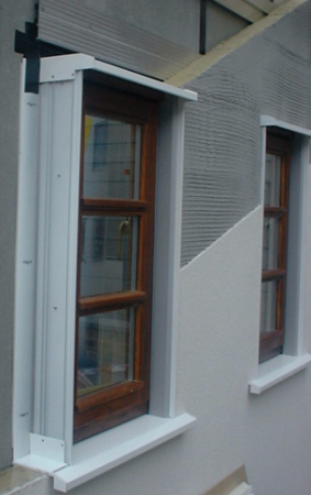
Window pod detail used with insulated render


[top]Wind resistance


Wind loads on facades of building are obtained from BS 6399-2[11] and to BS EN 1991-1-4[12] and its National Annex[13]. (See here for further information). The two approaches are similar but use different terms to describe the topography, etc. The key parameters are the building location and its height, as wind pressures increase with height. A pressure coefficient of +0.85 is generally used for a windward face of a rectangular building combined with a negative internal pressure coefficient of -0.3. Higher wind pressures exist at the corners of the building. The design wind pressure acting on the façade may range between 0.8 and 1.5 kN/m2 for medium-rise buildings.
Resistance to positive or negative wind pressure is a primary requirement of light steel infill walls and therefore determines the depth, thickness and spacing of the C sections in the wall. The figure on the right shows the location of the light steel C sections around a large window opening. Pairs or groups of C sections may be required next to large openings.
Members A-A and B-B are designed for the wind pressure on the window and wall locally. For light steel infill walls, it is possible to use pairs of C sections or compound C sections (consisting of C and U sections ) to create long windows. Member C-C is designed in bending for the point loads transferred at points A and B and also from the adjacent wall. Again, it is possible to use pairs or triple C sections next to long windows.
The table below presents the number of C sections around windows of various widths when using 100 mm deep x 1.6mm thick C sections in walls of 2.4 to 3.6m height and for a 1 kN/m2 wind pressure. A maximum window width of about 3.5m is feasible for tall walls in this case.
| Wall height, L (m) | Window opening width, B (m) | ||||
|---|---|---|---|---|---|
| 1.5 | 2.0 | 2.5 | 3.0 | 3.5 | |
| 2.4 | 1V / 1H | 1V / 1H | 1V / 1H | 1V / 1H | 2V / 2H |
| 2.7 | 1V / 1H | 1V / 1H | 1V / 1H | 2V / 1H | 2V / 2H |
| 3.0 | 1V / 1H | 1V / 1H | 2V / 1H | 2V / 2H | 2V / 2H |
| 3.3 | 1V / 1H | 2V / 1H | 2V / 1H | 2V / 2H | 3V / 2H |
| 3.6 | 2V / 1H | 2V / 1H | 2V / 2H | 3V / 2H | 3V / 2H |
Key:
1V – Single C section either side of opening
2V – Pair of C sections either side of opening
3V – Three C sections either side of opening
1H – Single C section above and below opening
2H – Pair of C sections above and below opening
The table below presents the wall heights and window sizes that can be achieved when using 150mm deep x 1.6mm thick C sections. Wall heights of up to 5m can be designed with a maximum window width of about 5m in this case.
| Wall height, L (m) | Window opening width, B (m) | ||||
|---|---|---|---|---|---|
| 2.5 | 3.0 | 3.5 | 4.0 | 4.5 | |
| 3.0 | 1V / 1H | 1V / 1H | 1V / 1H | 1V / 1H | 1V / 1H |
| 3.5 | 1V / 1H | 1V / 1H | 1V / 1H | 1V / 1H | 1V / 2H |
| 4.0 | 1V / 1H | 1V / 1H | 1V / 1H | 2V / 1H | 2V / 2H |
| 4.5 | 1V / 1H | 2V / 1H | 2V / 1H | 2V / 2H | 2V / 2H |
| 5.0 | 2V / 1H | 2V / 1H | 3V / 1H | 3V / 2H | 3V / 2H |
Key:
1V – Single C section either side of opening
2V – Pair of C sections either side of opening
3V – Three C sections either side of opening
1H – Single C section above and below opening
2H – Pair of C sections above and below opening
[top]Cladding systems and interfaces
Interfaces between the light steel infill walls and the building envelope occur at the following locations:
- At the supporting structure, i.e. edge beams or floor slab
- Details associated with the facade material, for example at windows, when using brickwork or lightweight cladding
- At balconies and other penetrations.
The following description of the various types of cladding and support conditions is relevant to the design of infill walls and their interfaces with other elements of the building.
[top]Infill walls supported by beams or floor slab
The wind forces acting on the wall are transferred to the floor slab above and below via U-shaped sections (tracks) into which the C sections sit. Shot fired pins at 600 mm centres have sufficient shear resistance to transfer these forces to the supports. The top track is generally 2mm thick as it has to allow for relative movement between the infill walls and the supporting structure. The bottom track can be thinner and is typically 1.2mm thick.
The general rule for the allowance for movement depends on the span of the edge beam or floor slab. It also takes into account the likely structural movement over time. The following allowances for relative movement should be made at the top of the wall.
- For steel structures - Beam span/500 or 10 mm whichever is the greater.
- For concrete structures - Beam span/300 or 20 mm whichever is the greater.
This assumes that the self weight of the floor slab is already applied to the edge beams and that the cladding is lightweight or the brickwork is ground supported. The higher value for concrete structures is due to the effects of creep under its self weight load.
[top]Infill walls supporting external leaf of brickwork

Brickwork may be ground supported or supported at each floor. In both cases, the infill wall provides only lateral support via wall ties attached in vertical ‘runners’ that are screw fixed through the insulation to the C sections.
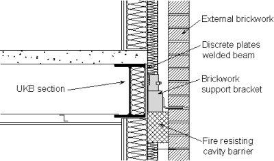
For buildings more than 3 or sometimes 4 storeys high, the brickwork is supported by proprietary stainless steel angles that are attached to the edge beams as shown below. A typical cross-section through an external wall using stainless steel angle supports is also shown.
The use of brickwork at ground floor level and various forms of lightweight cladding above should allow for a ‘step-out’ and flashings at the brickwork, which is thicker than the cladding above. In addition, balconies or access walkways often project from the façade, and their attachment represents a local detailing problem.
[top]Infill wall supporting light weight cladding

Various forms of lightweight cladding may be used with light steel infill walls, as follows:
- Insulated render that is bonded to a sheathing board and sometimes a small cavity is also provided
- Rain-screen cladding, that may be in the form of boards , metallic sheets or tiles attached to horizontal rails
- Metallic systems, such as composite panels (also known as sandwich panels), to which horizontal rails may be attached to provide support for terracotta tiles, etc.
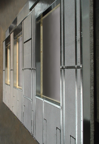
Some examples of lightweight cladding attached to infill walls are shown in the figures on the right. In most uses of rain–screen cladding, a sheathing board is attached to the external face of the infill walls to provide for weather resistance, both in the construction and in-service conditions. The sheathing board also adds to the air-tightness of the façade. It may be in the form of cement particle boards, calcium silicate board or, for insulated render applications, moisture resistant plasterboard.
Insulated render attached to light steel infill walls
Metallic rain-screen cladding attached to light steel infill walls


[top]Performance requirements for separating walls
Separating walls have different performance requirements to external walls and are described as follows
[top]Acoustic performance
In residential buildings, hospitals, and schools, it is necessary to provide acoustic attenuation (insulation) to airborne sound transfer between occupancies or specialist rooms. Double layer separating walls are generally specified where a high level of acoustic attenuation is required.
In residential buildings, the required level of acoustic attenuation between rooms is defined by a sound reduction index (DnTw + Ctr) which includes a low frequency correction factor (Ctr). For airborne sound, the minimum limit in Approved Document E[14] is 45dB, which is consistent with a figure of around 55dB without considering the low frequency correction factor.
In hospitals, Health Technical Memorandum HTM 08-01[15] sets out the recommended acoustic criteria for the design and management of new healthcare facilities. For noise level in rooms, there are two criteria; external noise intrusion and mechanical services noise. The criteria for the former are internal equivalent continuous sound pressure level (LAeq) targets over typical 1-hour daytime periods (and also night-time for wards). Targets for maximum noise levels (LAmax) are also set for wards and operating theatres. Refer to the table below.
| Room | External noise intrusion criteria (dB) |
|---|---|
| Ward – single person | 40 LAeq, 1hr daytime |
| 35 LAeq, 1hr night | |
| 45 LAmax, f night | |
| Ward – multi-bed | 45 LAeq, 1hr daytime |
| 35 LAeq, 1hr night | |
| 45 LAmax, f night | |
| Open clinical areas | 45 LAeq, 1hr |
| Circulation spaces | 55 LAeq, 1hr |
| Public areas | 50 LAeq, 1hr |
| Small meeting rooms | 40 LAeq, 1hr |
| Operating theatres | 40 LAeq, 1hr |
| 50 LAmax, f | |
| Laboratories | 45 LAeq, 1hr |
For mechanical services, Noise Rating (NR) levels are recommended, although these exclude noise from specialist medical equipment. For offices, there are no specific criteria for airborne sound reduction between occupancies but the same figures as for residential buildings would normally be considered reasonable.
The acoustic performance of light steel separating walls is presented in the table below. Where higher levels of acoustic insulation are required, the plasterboard lining can be upgraded, e.g. by using sound insulating boards rather standard wall board or by increasing the number of layers. More guidance on acoustic detailing of light steel separating walls is given in SCI P372.
| Form of construction | Airborne sound reduction, DnT, w + Ctr (dB) |
|---|---|
| Single leaf wall with single layer of 12mm plasterboard on each side | 39 |
| Single layer wall with resilient bars and two layers of 15mm plasterboard on both sides and mineral wool quilt placed between the studs | 48 |
| Double layer wall with insulation quit in the cavity and two layers of 15mm plasterboard on the outer faces | 50 |
| Double layer wall with insulation quit between the C sections and two layers of 15mm plasterboard on the outer faces | 52 |
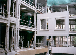
A typical light steel separating walls is shown. Insulating quilt or mineral wool may be placed between the leaves or between the C sections in both leaves of the wall. Two layers of 15mm thick 'fire resisting' plasterboard (conforming to BS EN 520[2], Type F) are placed either side of the wall. This same wall build-up for acoustic insulation achieves at least 60 minutes fire resistance.
Special details are required at the junction with the composite floor slab or internal beams to prevent unwanted flanking acoustic losses that reduce the effective sound reduction that is achieved. A typical detail is shown below.

Typical light steel separating walls showing acoustic insulation placed between the double leaf walls

Detailing of light steel separating walls with a composite floor slab.


[top]Fire resistance of separating walls
For external walls, Approved Document B[4] (England) specifies the required period of fire resistance. The measures introduced for acoustic insulation are generally sufficient to achieve the most commony required levels of fire resistance in non-load bearing applications. Two layers of fire resistant plasterboard (conforming to BS EN 520[2], Type F) are sufficient to provide 90 minutes fire resistance for a separating wall.
[top]Load resistance of internal walls
The design of internal walls depends on their application, e.g. heavy duty or medium duty, etc as defined in BS 5234-2[16]. For medium duty applications, which is relevant to most general use buildings, the design loading is 0.5 kN/m2 for which the maximum deflection is 20mm. A further criterion is an impact load due to a soft weight ( a 50kg swinging bag) for which the residual deformation should be less than 2mm. The height: width ratio of a C section used in a separating walls is typically up to 40, and it is found that the plasterboard adds significantly to the stiffness of the C sections (by up to 100%).
[top]References
- ↑ BS EN 10346:2015. Continuously hot-dip coated steel flat products. Technical delivery conditions. BSI
- ↑ 2.0 2.1 2.2 2.3 2.4 BS EN 520:2004+A1:2009 Gypsum plasterboards. Definitions, requirements and test methods. BSI
- ↑ 3.0 3.1 Approved Document L2A (Conservation of fuel and power in new buildings other than dwellings) 2013 Edition incorporating 2016 amendments. Department for Communities and Local Government
- ↑ 4.0 4.1 Approved Document B (Fire safety, Volume 2 – Buildings other than Dwellinghouses), 2006 Edition incorporating 2007, 2010 and 2013 amendments. Department for Communities and Local Government
- ↑ BS EN 13501-1:2018 Fire classification of construction products and building elements. Classification using data from reaction to fire tests, BSI
- ↑ 6.0 6.1 6.2 Approved Document C (Site preparation and resistance to contaminates and moisture) 2004 Edition incorporating 2010 and 2013 amendments. Department for Communities and Local Government
- ↑ BS 8104:1992. Code of practice for assessing exposure of walls to wind-driven rain. BSI
- ↑ BS 5628-3:2005. Code of Practice for design of masonry. Materials, components, design and workmanship, BSI
- ↑ BS EN 13830:2015 Curtain walling. Product standard, BSI
- ↑ BS EN 13050:2011 Curtain Walling. Watertightness. Laboratory test under dynamic condition of air pressure and water spray, BSI
- ↑ BS 6399-2:1997. Loading for Buildings: Code of practice for wind loads. BSI
- ↑ BS EN 1991-1-4:2005+A1:2010 Eurocode 1. Actions on structures. General actions. Wind actions. BSI
- ↑ NA to BS EN 1991-1-4:2005+A1:2010 UK National Annex to Eurocode 1. Actions on structures. General actions. Wind actions. BSI
- ↑ Approved Document E (Resistance to the passage of sound) 2003 Edition incorporating 2004, 2010, 2013 and 2015 amendments. Department of Communities and Local Government
- ↑ Health Technical Memorandum 08-01, Acoustics. Department of Health, 2013
- ↑ BS 5234-2: 1992. Partitions (including matching linings): Specification for the performance requirements for strength and robustness including methods of test, BSI
[top]Further reading
- Structure and Fabric Part 1 Stround Foster, J, Mitchell’s Building Construction, William Clowes & Sons, 1973.
- BS EN ISO 140-4: 1998 Acoustics. Measurement of sound insulation in buildings and of building elements. Field measurements of airborne sound insulation between rooms. British Standards Institute, 1998.
- BS EN ISO 717: 1997 Acoustics. Rating of sound. British Standards Institute, 1997.
[top]Resources
- SCI P283: Benefits of Light Steel Framing in Rapid Dry Envelope
- SCI P101: Curtain Wall Connections to Steel Frames
- SCI P343: Insulated Render Systems Used With Light Steel Framing
- SCI P372: Acoustic Detailing for Steel Construction
- SCI ED013 Light Steel Infill Walls, 2012
- SCI ED017 Design and installation of light steel external wall systems, 2013
[top]See also
- Acoustics
- Acoustic performance of walls
- Acoustics regulations
- Fire and steel construction
- Structural fire resistance requirements
- Facades and interfaces
- Steel construction products
- Healthcare Buildings
- Education Buildings
- Commercial buildings
- Junction details for acoustic performance