


Junction details for acoustic performance
This article presents junction details appropriate for both light steel and hot-rolled construction between wall and floor elements. For each junction detail type, e.g. separating wall with separating floor, generally only one wall and one floor construction is considered. Due to the range of wall and floor constructions, it is impracticable to include junction details for all the possible combinations. The details that are included show the level of detailing that is required at the junctions and give principles that can be applied to junctions which are not shown. The details are provided for guidance and should not be used for construction unless checked and approved by a competent person such as an acoustic consultant. Light steel frame system suppliers will generally have their own specific junction details that they have developed and that have shown to be satisfactory through on-site testing.
Further information and guidance may be found in SCI P372.

[top]Reducing flanking sound transmission
It is important that the junctions are detailed correctly to minimise the transmission of flanking sound.
To reduce flanking sound transmission the following measures are suggested:
- Direct contact between the wall lining and floor finish board should be avoided, to reduce vibration transfer. Wall plasterboard linings should be stopped about 5 mm above the floor decking. The gap should be filled with acoustic sealant for light steel separating floors.
- Where a separating floor meets an external or party wall, the void within the wall between the studs should be filled with mineral wool to at least 300 mm above and below the separating floor.
- A light steel frame inner leaf structure of an external wall should not be continuous across a junction with a separating wall. A physical break should be maintained, and any sheathing board should also be discontinuous at this.
- Where a separating wall meets an internal wall or external wall, additional mineral wool should be placed between the wall studs adjacent to the junction of the inner leaf of the external wall. However, in many cases, the inner leaf of the external wall will be filled with mineral wool for thermal insulation.
- Internal non-load bearing walls within an apartment should, if possible, not break through the ceiling of a separating floor, and should not touch the steel floor joists.
- Air paths through separating elements should be avoided.
- Joints in successive layers of lining board should be staggered.
- Any gaps should be sealed with acoustic sealant.
The details generally assume that light steel frame separating walls in light steel framed buildings are load bearing. Internal walls can be load bearing or non-load bearing.
Junction details are a significant part of acoustic detailing and are included in the Robust Details Handbook[1].
[top]Separating wall with separating floor
[top]Light steel separating floor
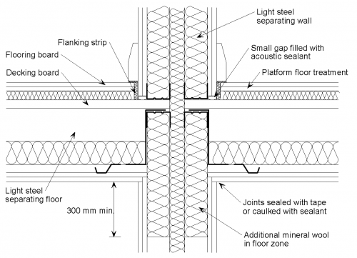

The following detailing should be applied at the junction of a twin light steel frame separating wall with a light steel joist with board separating floor:
- The wall boards are not in direct contact with the floor decking board or the flooring board.
- The gap between the wall boards and the decking board is filled with acoustic sealant.
- The joints between wall boards and the ceiling boards are sealed with tape or caulked with sealant.
- Additional mineral wool is placed between the wall studs in the floor zone.
There is a range of suitable floor treatments that can be applied to a light steel joist floor.
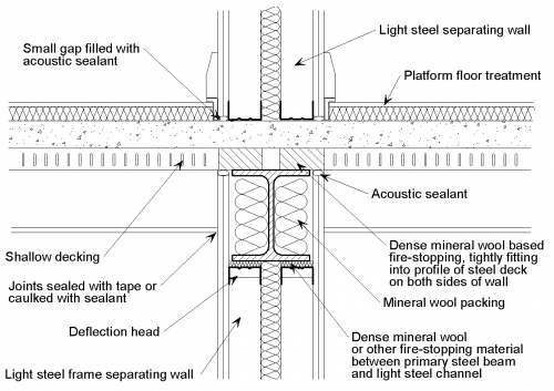
[top]Composite separating floor
The following detailing should be applied at the junction of a twin light steel frame separating wall with a shallow composite separating floor:
- The wall boards are not in direct contact with the floor treatment or the composite slab.
- The decking may span in either direction but where decking profiles are at right angles to the walls the voids (above the beam) are filled with profiled mineral wool inserts and caulked with acoustic or flexible sealant.
- The gap between the wall boards and the slab is filled with acoustic sealant.
- The joints between wall boards and the ceiling boards are sealed with tape or caulked with sealant.
- Ceiling and wall boards should not be in direct contact with any steel beams or columns.
- Floor treatment should not be continuous under separating wall.

[top]Separating wall with internal floor
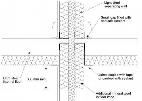

The following detailing should be applied at the junction of a twin light steel frame separating wall with a light steel joist internal floor:
- The wall boards are not in direct contact with the flooring board and the gap is filled with acoustic sealant.
- The joints between wall boards and the ceiling boards are sealed with tape or caulked with sealant.
- Additional mineral wool is placed between the wall studs in the floor zone.
- The floor joists may span in either direction but should not be continuous between dwellings.
[top]Junctions between two separating walls

At a ‘T’ junction between two twin light steel frame separating walls the joints between wall boards are sealed with tape or caulked with sealant.
Incorporating a steel column into a ‘T’ junction is easily achievable whilst maintaining the acoustic performance.
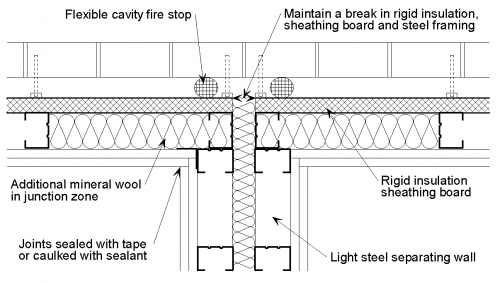
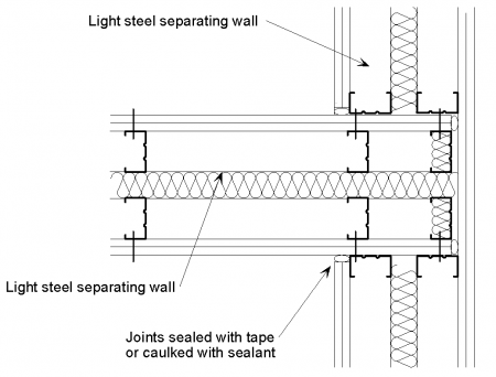
[top]Separating wall with external wall
The following detailing should be applied at a junction between a twin light steel frame separating wall and an external wall with a light steel inner leaf:
- The light steel frame inner leaf and rigid insulation sheathing board are discontinuous at the junction with the separating wall.
- Joints between wall boards are sealed with tape or caulked with sealant.
- Additional mineral wool (if not already part of the wall construction) is placed between the wall studs in the junction zone.
Incorporating a steel column into a junction is easily achievable whilst maintaining the acoustic performance.
[top]Separating wall with internal wall
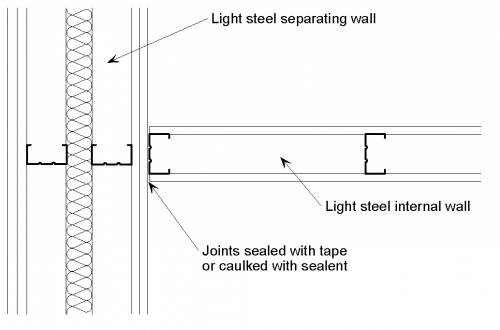

The following detailing should be applied at a junction between a twin light steel frame separating wall and a light steel internal wall:
- The structure of the separating wall, including the wall linings, is maintained through the junction.
- The joints between wall boards are sealed with tape or caulked with sealant.
The same detailing principals would be applicable for any light steel internal wall construction.
[top]Separating floor with external wall
[top]Light steel separating floor
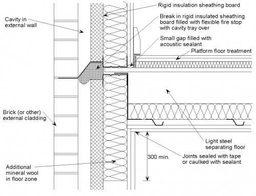

The following detailing should be applied at the junction of a light steel joist separating floor with an external cavity wall with a light steel inner leaf:
- The wall boards are not in direct contact with the floor decking board or the flooring board.
- The gap between the wall boards and the decking board is filled with acoustic sealant.
- The joints between wall boards and the ceiling boards are sealed with tape or caulked with sealant.
- Additional mineral wool (if not already part of the wall construction) is placed between the wall studs in the floor zone.
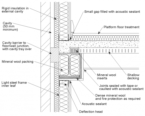
[top]Composite separating floor
The following detailing should be applied at the junction of a shallow composite separating floor with an external cavity wall with a light steel inner leaf:
- The wall boards are not in direct contact with the floor treatment or the composite slab.
- The decking may span in either direction but where decking profiles not parallel with the walls the voids (above the beam) are filled with profiled mineral wool inserts and caulked with acoustic or flexible sealant.
- The gap between the wall boards and the slab is filled with acoustic sealant.
- The joints between wall boards and the ceiling boards are sealed with tape or caulked with sealant.
- Ceiling and wall boards should not be in direct contact with any steel beams or columns.
- Inner leaf must not be continuous between storeys.

[top]Separating floor with internal wall
[top]Load bearing internal wall
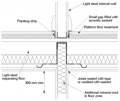

The following detailing should be applied at the junction of a load bearing light steel frame internal wall with a light steel joist with board separating floor:
- The wall boards are not in direct contact with the floor decking board or the flooring board.
- The gap between the wall boards and the decking board is filled with acoustic sealant.
- The joints between wall boards and the ceiling boards are sealed with tape or caulked with sealant.
- Additional mineral wool (if not already part of the wall construction) is placed between the wall studs in the floor zone.
The floor treatment may be continuous or discontinuous under the internal wall. However, if the floor treatment is continuous under the internal wall, adequate support should be provided. Product manufacturers should be consulted to determine adequate support.
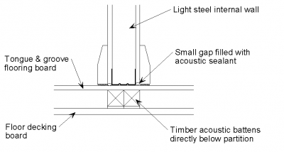

[top]Non-load bearing wall
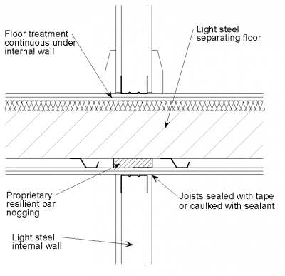

The following detailing should be applied at the junction of a non-load bearing light steel frame internal wall with a light steel joist with board separating floor:
- The joints between wall boards and the ceiling boards are sealed with tape or caulked with sealant.
- The ceiling board of the separating floor is continuous through the junction with the internal wall and the internal wall is isolated from the light steel floor joists.
[top]Internal wall with internal wall
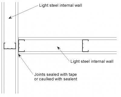

The junction between two light steel frame internal walls is a simple detail. The joints between wall boards are sealed with tape or caulked with sealant.
[top]References
[top]Further reading
- Carl Hopkins. Sound insulation. Elsevier, Butterworth-Heinemann, 2007.
- M.W. Simons & J. R. Waters. Sound Control in Buildings. A guide to Part E of the Building Regulations. Blackwell publishing, 2004.
- BS EN ISO 10140: 2010 Acoustics. Laboratory measurement of sound insulation of building elements. Various parts. British Standards Institution.
- BS EN ISO 717: 2013 Acoustics. Rating of sound insulation in buildings and of building elements. Various parts. British Standards Institution.
[top]Resources
- SCI P372 Acoustic Detailing for Steel Construction
- SCI P320 Acoustic performance of light steel framed systems
- SCI P322 Acoustic performance of composite floors
- SCI P336 Acoustic detailing for multi-storey residential buildings
- SCI P371 Acoustic performance – Case Studies
- SCI Advisory Desk AD 313. Precast concrete floors in steel framed buildings: Achieving floor diaphragm action and acoustic performance
- SCI Acoustic performance prediction tool for separating floors and walls
[top]See also
- Introduction to acoustics
- Acoustic regulations
- Acoustic performance of walls
- Acoustic performance of floors
- Integration of elements for acoustic performance
- Steel construction products
- Composite construction