


Member design
This article describes the verification of steel members subject to shear, bending moments and axial forces. The member must provide adequate compression, tension, bending and shear resistance. Where the member is subjected to axial and bending simultaneously, additional resistance checks will be required, taking into account the combination of these loading effects.
Member design follows the requirements given in BS EN 1993-1-1[1]. The overall process of member design includes:
- Classification of cross sections
- Cross-section resistance
- Member buckling (buckling under axial compression or lateral torsional buckling under bending)
- Combined axial loading and bending, where applicable.
SCI P362 forms the background to the member design presented in this article and provides more comprehensive guidance.
[top]Partial factors for resistance
The partial factors γM that are applied to the various characteristic values of resistance in member design are:
- Resistance of cross-section: γM0 = 1.00
- Resistance of members to instability: γM1 = 1.00 (used in buckling resistance)
- Resistance of cross-sections in tension to fracture: γM2 = 1.10
The values are those given in the UK National Annex to BS EN 1993-1-1[2].
[top]Classification of cross sections
Four classes of cross-sections of are defined in BS EN 1993-1-1[1]:
- Class 1 cross-sections are those which can form a plastic hinge with the rotation capacity required for plastic analysis without reduction of the resistance.
- Class 2 cross-sections are those which can develop their plastic moment resistance, but which have limited rotation capacity because of local buckling.
- Class 3 cross-sections are those in which the stress in the extreme compression fibre of the steel member assuming an elastic distribution of stresses can reach the yield strength, but local buckling prevents development of the plastic moment resistance.
- Class 4 cross-sections are those in which local buckling will occur before the attainment of yield stress in one or more parts of the cross-section.
The class of the cross section is determined from Table 5.2 of BS EN 1993-1-1[1] , where a cross section is classified according to the highest (least favourable) class of its parts subject to compression. See also SCI P362 .
Section classification is also given in resistance tables, such as SCI P363 (the 'Blue Book' ). SCI P363 gives axial load ratios where (under increasing levels of axial load) a section becomes Class 3 and Class 4. The level of axial load at which a section becomes Class 2 is not required because the same section properties (the gross area and plastic modulus) are used in the resistance calculations for both Class 1 and Class 2 sections.
Class 4 cross sections are not considered in this article.
[top]Resistance of cross sections
[top]General
The design value of an action effect in each cross-section should not exceed the corresponding resistance and if several action effects act simultaneously, the combined effect should not exceed the resistance for that combination. As a conservative approximation for all cross-sections, a linear summation of the utilization ratios for each resistance may be used. For the combination of NEd, My,Ed and Mz,Ed this method may be applied using the following criteria:
![]()
NRd, My,Rd and Mz,Rd are the design values of the resistance depending on the cross-sectional classification and including any reduction that might be caused by shear effects.
More generally, the Eurocodes provide specific clauses for common combined effects (for example bending and shear, bending and axial force and bending, shear and axial force) which should be used in preference to this simplified approach.
[top]Material strength
According to the UK National Annex to BS EN 1993-1-1[2], yield strength fy and ultimate strength fu must be taken from the product standard, not Table 3.1 of the design standard. Moreover, if a range of ultimate strengths is given in the product standard, the lowest value must be adopted. Yield strengths and ultimate strengths for hot-rolled steelwork are given in BS EN 10025-2[3].
[top]Section properties
[top]Gross cross-section
The properties of the gross cross-section should be determined using the nominal dimensions. Holes for fasteners need not be deducted, but allowance should be made for larger openings. Splice materials should not be included.
[top]Net sections
The net area of a cross section should be taken as its gross area less appropriate deductions for all holes and other openings. For calculating net section properties, the deduction for a single fastener hole should be the gross cross-sectional area of the hole in the plane of its axis. For countersunk holes, appropriate allowance should be made for the countersunk portion.
[top]Tension
The design value of the tension force NEd at each cross-section should satisfy:
![]()
For sections without holes, the design tension resistance Nt,Rd should be taken as the design plastic resistance of the gross cross-section:

where
- A is the gross cross section
For sections with holes, the design tension resistance Nt,Rd should be taken as the smaller of:
- The plastic resistance of the gross cross-section (given above); and
- The design ultimate resistance of the net cross-section at holes for fasteners:

For angles connected through one leg, refer to BS EN 1993-1-8[4] Clause 3.10.3.
Similar consideration should also be given to other types of sections connected through outstands.
[top]Compression
The design value of the compression force NEd at each cross-section should satisfy:
![]()
The design resistance of the cross-section for uniform compression Nc,Rd should be determined as follows:
![]() for class 1, 2 or 3 cross-sections
for class 1, 2 or 3 cross-sections
Section classification is given in resistance tables, such as SCI P363 (the 'Blue Book').
For members of uniform cross-sections in axial compression the design buckling resistance, Nb,Rd almost always governs.
Compression resistance design tool
[top]Bending
The design value of the bending moment MEd at each cross-section should satisfy:
![]()
Where the design resistance for bending about one principal axis of a cross-section Mc,Rd is determined as follows:
![]() for Class 1 or 2 cross-sections
for Class 1 or 2 cross-sections
![]() for Class 3 cross-sections
for Class 3 cross-sections
and
- Wel,min corresponds to the fibre with the maximum elastic stress.
For bending about both axes, the following criterion may be used for I and H sections.

Bending resistance design tool
[top]Torsion
Beams subject to loads which do not act through the point on the cross-section known as the shear centre normally suffer some twisting. For doubly symmetrical sections such as UB or UC, the shear centre coincides with the centroid, while for channels it is situated on the opposite side of the web from the centroid.
If torsion cannot be avoided, a torsionally stiff section, such as a hollow section, is recommended. The twist of an open section may be very significant and must be considered if this type of section is used.
More information on torsional resistance is given in SCI P385.
[top]Shear
The design value of the shear force VEd at each cross-section should satisfy:
![]() where:
where:
- Vc,Rd is the design plastic shear resistance Vpl,Rd.
In the absence of torsion, the design plastic shear resistance is given by:
![]() where:
where:
- Av is the shear area.
For rolled I and H sections, with load parallel to the web, the shear area Av is given by:
Av = A - 2b tf + (tw + 2r)tf
The shear resistance may be limited by shear buckling. For such situations, reference is to be made to BS EN 1993-1-5[5]. Shear buckling is rarely a consideration with hot rolled sections.
[top]Bending and shear
Where shear is present, allowance should be made for its effect on the bending resistance.
Where VEd < 0.5Vpl,Rd the effect of the shear force on the bending resistance may be neglected, except where shear buckling reduces the section resistance.
Where VEd ≥ 0.5Vpl,Rd the reduced moment resistance should be taken as the design resistance of the cross-section, calculated using a reduced yield strength for the shear area, given by:
(1 - ρ) fy
where:

and Vpl,Rd is calculated as described here.
[top]Bending and axial force
When an axial force is present, allowance should be made for its effect on the plastic moment resistance. For Class 1 and 2 cross-sections, the following criteria should be satisfied:
MEd ≤ MN,Rd
where:
- MN,Rd is the design plastic moment resistance reduced due to the axial force NEd.
For doubly symmetric I- and H-sections within certain limits, the effect of axial force may be neglected. This is covered in clause 6.2.9 of BS EN 1993-1-1[1]:
For Class 3 cross-sections the maximum longitudinal stress due to moment and axial force, taking account of fastener holes, where relevant, should not exceed fy/γMO.
Combined axial compression and bending resistance design tool
[top]Bending, shear and axial force
Where VEd ≤ 0.5Vpl,Rd, no reduction of the resistances defined for bending and axial force need be made.
Where VEd > 0.5Vpl,Rd, the design resistance of the cross-section to combinations of moment and axial force should be calculated using a reduced yield strength, as given for bending and shear.
[top]Buckling resistance of members
[top]Uniform members in compression
BS EN 1993-1-1[1] covers three modes of buckling when subject to axial compression:
- Flexural buckling (commonly known as strut buckling)
- Torsional buckling, which may be critical for cruciform sections subject to axial compression
- Torsional-flexural buckling, which may be critical for asymmetric sections subject to axial compression.
[top]Buckling resistance
A compression member is verified against buckling by the relationship:
![]() where:
where:
- NEd is the design value of the compression force
- Nb,Rd is the design buckling resistance of the compression member where:
![]() for Class 1, 2 and 3 cross-sections, and
for Class 1, 2 and 3 cross-sections, and
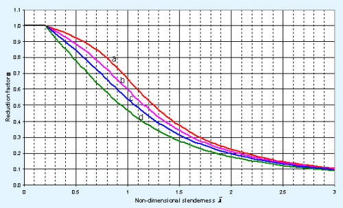
- χ is the reduction factor for the relevant buckling mode
The reduction factor χ is calculated from the non-dimensional slenderness ![]() and an imperfection factor, α
and an imperfection factor, α
The reduction factor χ is given by:
![]() but χ ≤ 1
but χ ≤ 1
where:
![]()
where α is the imperfection factor selected from Table 6.2 depending on member type, strength and axis of buckling.
The non-dimensional slenderness ![]() is given by:
is given by:
For Class 1, 2 and 3 cross sections,
 where Ncr is the elastic critical force for the relevant buckling mode.
For each mode of buckling, the value of Ncr is determined.
Open sections (UB, UC) (bi-symmetric sections) are not subject to torsional flexural buckling. Open sections do exhibit torsional buckling, but for any given length, minor axis flexural buckling is critical. SCI P363 (the Blue Book) provides flexural buckling resistances in both axes and the torsional buckling resistance.
For angles, an effective slenderness should be calculated from Annex BB.1.2 of BS EN 1993-1-1[1]. A similar effective slenderness can be calculated for channels which are only connected through the web.
See the Compression resistance design tool.
[top]Flexural buckling (only)


Permission to reproduce extracts from British Standards is granted by the British Standards Institution (BSI). No other use of this material is permitted. British Standards can be obtained in PDF or hard copy formats from the BSI online shop: http://shop.bsigroup.com or by contacting BSI Customer Services for hard copies only:
Tel: +44 (0)20 8996 9001, Email: cservices@bsigroup.com
For flexural, or strut buckling, Ncr, the elastic critical force, is equal to ![]() and the non-dimensional slenderness
and the non-dimensional slenderness ![]() is given by:
is given by:
![]() for Class 1, 2 and 3 cross-sections, where:
for Class 1, 2 and 3 cross-sections, where:
- Lcr is the buckling length in the axis considered
- i is the radius of gyration about the relevant axis, determined using the properties of the gross cross-section
- λ1 = 86 for grade S275 steel
- λ1 = 76 for grade S355 steel
The imperfection factor α corresponding to the appropriate buckling curve is obtained from the table below. The choice of buckling curve is obtained from the table to the right. For S460 steel consult Table 6.2.
| Buckling curve | a | b | c | d |
|---|---|---|---|---|
| Imperfection factor α | 0.21 | 0.34 | 0.49 | 0.76 |
The value of χ may be calculated, or may be obtained from a graph or a table. The graphical presentation is shown in the figure below, taken from SCI P362.

[top]Uniform members in bending
[top]Lateral torsional buckling resistance
A laterally unrestrained member subject to major axis bending is verified against lateral-torsional buckling by the relationship:
![]()
where:
- MEd is the design value of the moment
- Mb,Rd is the design buckling resistance moment.
Beams with sufficient restraint to the compression flange are not susceptible to lateral-torsional buckling.
The design buckling resistance of a laterally unrestrained beam is given by:
![]()
where:
- Wy is the appropriate section modulus as follows:
- Wy = Wpl,y for Class 1 and 2 cross-sections
- Wy = Wel,y for Class 3 cross-sections
- χLT is the reduction factor for lateral-torsional buckling.
See the Bending resistance design tool.
[top]Reduction factor for lateral torsional buckling of rolled sections
For rolled bi-symmetric sections the reduction factor χLT is calculated from the non-dimensional slenderness ![]() LT and an imperfection factor, αLT
LT and an imperfection factor, αLT
The reduction factor χLT is given by:
![]() but χLT ≤ 1
but χLT ≤ 1
where:
![]()
For rolled sections, the UK National Annex[2] specifies β = 0.75 and ![]() LT,0 = 0.4
LT,0 = 0.4
The non-dimensional slenderness ![]() LT is given by:
LT is given by:
 where:
- Wy is the appropriate section modulus for the section classification
- Mcr is the elastic critical moment for lateral-torsional buckling
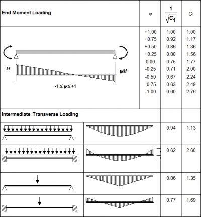

An expression to evaluate Mcr is not given in BS EN 1993-1-1[1], however, methods which enable Mcr to be determined include:
Method 1
NCCI document SN003 provides appropriate expressions to calculate Mcr. For loads which are not destabilizing, and for doubly symmetric sections, i.e. UB and UC :

where:
- E, G are material properties
- Iz, It, Iw are section properties obtained from SCI P363 (the Blue book)
- L is the buckling length of the member
- C1 is a factor that depends on the shape of the bending moment diagram - see figure on the right.
Method 2
Mcr may be determined using the software LTBeam.
Alternatively, Mcr may be determined using the Elastic critical moment for lateral-torsional buckling (Mcr) calculation tool.
Other (simplified) approaches are described in SCI P362 Section 6.3.2.3.
The value of the imperfection parameter αLT corresponding to the appropriate buckling curve is given by the table below and the choice of buckling curve given in the subsequent table.
| Buckling curve | a | b | c | d |
|---|---|---|---|---|
| Imperfection factor αLT | 0.21 | 0.34 | 0.49 | 0.76 |
| Cross-section | Limits | Buckling curve |
|---|---|---|
| Rolled doubly symmetric I and H sections and hot finished hollow sections |
h/b ≤ 2 | b |
| 2 < h/b ≤ 3.1 | c | |
| h/b > 3.1 | d | |
| Angles (for moments in the major principal plane) | d | |
| All other hot-rolled sections | d | |
| Cold-formed hollow sections | h/b ≤ 2 | c |
| 2 ≤ h/b < 3.1 | d |
The lateral torsional buckling curves for rolled sections are shown in the figure below, taken from SCI P362.
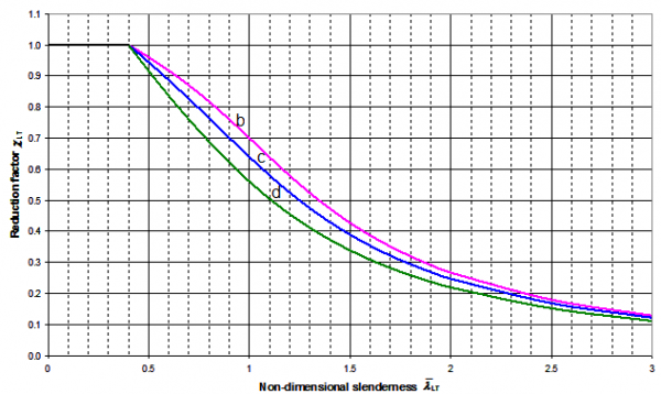

Having calculated λLT and selected the appropriate curve, the reduction factor χLT may be calculated or determined from look-up tables in SCI P362, or by using the above figure.
[top]Uniform members in bending and axial compression
For members of structural systems, verification of buckling resistance of doubly symmetric cross-sections may be carried out on the basis of the individual single span members regarded as cut out of the system. Second order effects of the sway system (P-Δ effects) should be taken into account, either by the end moments of the member or by means of appropriate buckling lengths about each axis for the global buckling mode.
Members which are subjected to combined bending and axial compression should satisfy:

Where:
- NEd, My,Ed and Mz,Ed are the design values of the compression force and the maximum moments about the y-y and z-z axes along the member, respectively
- Nb,y,Rd and Nb,z,Rd are the design buckling resistances of the member about the major and minor axis respectively
- Mb,Rd is the design buckling resistance moment
- Mcb,z,Rd
 for Class 1 and 2 sections
 - Mcb,z,Rd
 for Class 3 sections
 - kyy, kyz, kzy, kzz are interaction factors, which may be determined from Annex A or B of BS EN 1993-1-1[1].
Annex B is recommended as the simpler approach for manual calculations. Use of either Annex is permitted by the UK National Annex[2].
In some cases, a conservative value of the k factors may be sufficient for initial design. The following table gives maximum values, based on Annex B of the Standard, and assuming the sections are susceptible to torsional deformations, i.e. not hollow sections.
| Interaction factor | Maximum values | |
|---|---|---|
| Class 3 | Class 1 and 2 | |
| kyy | Cmy × 1.6 | Cmy × 1.8 |
| kyz | kzz | 0.6 × kzz |
| kzy | 1.0 | 1.0 |
| kzz | Cmz × 1.6 | Cmz × 2.4 |
The equations to calculate the interaction factors are given in SCI P362 Appendix D. A series of graphs are provided in SCI P362 from which accurate values of the interaction factors may be determined as an alternative to calculation.
See the Combined axial compression and bending resistance design tool.
[top]Columns in simple construction
Design of columns in simple construction is based on NCCI document SN048 in which a column in simple construction subject to nominal bending moments and axial compression may be verified using simplified interaction criteria.
See the Columns in simple construction design tool.
[top]References
- ↑ 1.0 1.1 1.2 1.3 1.4 1.5 1.6 1.7 BS EN 1993-1-1:2005+A1:2014, Eurocode 3: Design of steel structures. General rules and rules for buildings, BSI
- ↑ 2.0 2.1 2.2 2.3 NA to BS EN 1993-1-1:2005+A1:2014, UK National Annex to Eurocode 3: Design of steel structures General rules and rules for buildings, BSI
- ↑ BS EN 10025-2:2019 Hot rolled products of structural steels. Technical delivery conditions for non-alloy structural steels, BSI.
- ↑ BS EN 1993-1-8:2005. Eurocode 3: Design of steel structures. Design of joints, BSI
- ↑ BS EN 1993-1-5:2006+A2:2019. Eurocode 3: Design of steel structures Plated structural elements. BSI
[top]Further reading
- LTBeam is a software tool which deals with the elastic 'Lateral Torsional Buckling of Beams' under bending action about their major axis.
- Steel Designers' Manual 7th Edition. Editors B Davison & G W Owens. The Steel Construction Institute 2012, Chapters 14, 15, 16, 17 and 19
[top]Resources
- SCI P361 Steel Building Design: Introduction to the Eurocodes, 2009
- SCI P362 Steel Building Design: Concise Eurocodes, 2009
- SCI P363 Steel Building Design: Design Data, 2013
A web-based interactive version of the 'Blue Book', is also available. - SCI P364 Steel Building Design: Worked Examples - Open Sections, 2009 (A 2017 revised edition is available from SCI)
- SCI P385 Design of steel beams in torsion, 2011.
- NCCI: SN003b-EN-EU Elastic critical moment for lateral torsional buckling.
- NCCI: SN048b-EN-GB Verification of columns in simple construction - a simplified interaction criterion.
Member design tools:
- Compression resistance design tool
- Bending resistance design tool
- Combined axial compression and bending resistance design tool
- Columns in simple construction design tool
- Elastic critical moment for lateral torsional buckling calculation tool
- Concrete filled structural hollow section design tool
[top]See also
- Steel construction products
- Design codes and standards
- Modelling and analysis
- Design software and tools