


Multi-storey office buildings
The dominance of steel in the multi-storey commercial sector is based on tangible client-related benefits including the ability to provide column free floor spans, efficient circulation space, integration of building services, and the influence of the site and local access conditions on the construction process. For inner city projects, speed of construction and minimum storage of materials on-site require a high level of pre-fabrication, which steel-framed systems can provide.
There is a strong demand for high quality office space, especially in city centres. Corporate headquarters for banks and other high profile companies require that buildings are built to high architectural and environmental standards. Investment ‘value’ is the main criterion for choice of the building architecture, form and servicing strategy. Many buildings are curved or of complex architectural form, and have highly glazed façades and atria.
In many large commercial buildings, a two stage construction process means that the tenant is responsible for the servicing and fit-out, and so the building structure has to be sufficiently flexible to cope with these differing requirements. Many smaller buildings are designed for natural ventilation and with a high proportion of renewable energy technologies built into them. Many solutions are possible using steel construction.
- Cefas Lowerstoft-1a.jpg
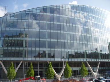
- 80 Charlotte Street-1a.jpg
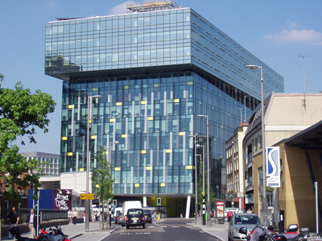
- Circle Square Nos 2 and 4-1a.jpg


[top]Attributes of steel construction
Main articles: The case for steel, Service integration, Cost of structural steelwork, Cost planning through design stages, Cost comparison studies, Health and safety
The commercial sector demands buildings that are rapid to construct, of high quality, flexible and adaptable in application, and energy efficient in use. Steel, and in particular, composite construction has achieved over 70% market share in this sector in the UK where the benefits of long spans: speed of construction; service integration; improved quality; and reduced environmental impact are widely recognised.
The overall building economics are fundamental on the rationale for using steel construction in the commercial building sector, where the market share for steel has been consistently 65 to 70% for the last 20 years.
[top]Value for money
Recent cost comparison studies show that the building superstructure generally accounts for only 10% to 15% of the total building cost and that the influence of the choice of structure on the foundations, services and cladding costs is often more significant. For example, a reduction of 100 mm in the ceiling to floor zone can lead to a 2.5% saving in cladding cost (equivalent to 0.5% saving in overall building cost).
Therefore, best practice building design requires a synthesis of architectural, structural, services, logistics and constructional issues. Where this synthesis has been achieved, long-span steel systems with provision for service integration dominate commercial building design.
The results of a recent independent cost comparison study of multi-storey commercial buildings can be seen here.
| Factor | Improvement | Economic benefit |
|---|---|---|
| Speed of construction | 20 to 30% reduction in construction time relative to site-intensive construction, depending on the scale of the project. | The economic benefit depends on the business operation. In terms of overall building cost, a saving of 1% in interest charges, and 2% in early rental or use of the space is predicted. |
| Site management costs | Site management costs are reduced because of the shorter construction period, and the packaged nature of the construction process. | Site management costs can be reduced by 20 to 30% which can lead to a 3 to 4% saving in terms of overall building cost. |
| Service integration | The integration of services in the structural zone leads to reduction of 100 to 300mm in floor to floor zone and hence to savings in cladding cost. | A 5% reduction in floor to floor height can lead to one additional floor in 20, and to a similar reduction in cladding cost, which is equivalent to about 1% in total building cost. |
| Foundations | Steel construction is less than half the weight of an equivalent concrete structure, which is equivalent to a 30% reduction in overall foundation loads. | Foundation costs depend on the sub-structure and factors such as underground services and represent up to 5% of the building cost . A 30% reduction in foundation loads can lead to a significant overall saving in terms of construction cost. |
| Column free space | Long span steel construction provides more flexible use of space, which depends on the function of the building and its future uses. | A large column in the middle of the space leads to a loss of space of approximately 1m2, which represents about 1% of the floor area, and may lead to an equivalent loss of rental income. |
[top]Speed of construction
All steel construction uses pre-fabricated components that are rapidly installed on site. Short construction periods leads to savings in site preliminaries, earlier return on investment and reduced interest charges. Time related savings can easily amount to 3 to 5% of the overall project value, reducing the client’s requirements for working capital and improving cash flow. In many inner city projects, it is important to reduce disruption to nearby buildings and roads. Steel construction dramatically reduces the impact of the construction operation on the locality.
[top]Flexibility and adaptability
Long spans allow the space to be arranged to suit open plan offices, different layouts of cellular offices and variations in office layout throughout the height of the building. Where integrated beam construction is used, the flat soffit gives complete flexibility of layout allowing all internal walls to be relocated, leading to fully adaptable buildings.

[top]Service integration

Steel and composite structures can be designed to reduce the overall depth of the floor zone by integrating major services within the depth of the structure, and/or by achieving the minimum structure depth. This is important in cases in which the building height is restricted for planning reasons, or in renovation projects.
[top]Quality and safety
Off-site prefabrication improves quality by factory controlled production, and is less dependent on site trades and the weather. Working in a controlled, manufacturing environment is substantially safer than working on site. The use of pre-fabricated components reduces site activity for frame construction by up to 75%, thereby substantially contributing to overall construction safety.
[top]Sustainability

Many of the intrinsic properties of steel usage in construction have significant environmental benefits. For example, the steel structure is 100% recyclable, repeatedly and without any degradation, it can be reused, and the flexibility and adaptability of steel structures maximise the economic life of the building as it can accommodate radical changes in use, all of which are important in a drive to the circular economy. The speed of construction and reduced disruption of the site also gives local environmental benefits.
The structural efficiency of steel and composite construction leads to resource efficiency. For example, composite steel construction achieves the highest rating of A+ in the Green Guide to Specification.
Recent research under the Target Zero programme has confirmed that steel-framed commercial buildings can achieve low operational carbon targets and the highest BREEAM ratings cost effectively.
[top]Anatomy of commercial buildings
Main articles: Concept design
The anatomy of a commercial office building is a function of its size and location, and client and planning requirements. Some key aspects of building anatomy are described below. The common features that influence the building design are:
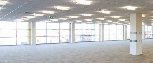
- Open plan areas that can be configured to suit the client requirements
- Partitioned space for executive offices, conference room etc. Partitions should be moveable for future re-configuration
- Communal space for toilets, kitchens, etc, which are often located near to service risers
- Access space for lifts, stairs and services maintenance, including means of escape in fire
- Featured space, such as the entrance lobby, atria, and penthouse
- Service plant areas which may be located on the roof or in the basement
- Below ground car parking in some cases.
[top]City centre commercial buildings

Commercial buildings in city centres tend to be relatively tall (6 to 12 storeys is a typical city centre project) because of the high cost of land and the confinement of adjacent buildings and utilities. Planning requirements have a strong impact on the building form and its architecture, and in many parts of the country, it is a planning objective that commercial buildings are required to generate a proportion of their on-site energy use from renewable sources, e.g. photovoltaics, heat pumps, CHP, CCHP, as in the Palestra building near Waterloo, London.
An important aspect of many modern commercial building developments is the need for retail space at ground floor, office space above, and in many cases, below ground car parking. This can lead to complexity in the alignment of planning grids from floor to floor. A common solution is to create a transfer structure at ground or first floor levels to optimise the space use above and below.
The sub-structure of city centre projects tends to be complex because of the high loads that are supported, the need to avoid affecting the foundations of neighbouring buildings, and to avoid obstructions and services in the ground. Piled foundations below basement level are most commonly used and the piles are placed in a group of typically 3 or 4 below a pile cap. There are various techniques to form basements including temporary sheet pile walls supported by steel H sections and contiguous bored pile walls.
Services also tend to be complex and some form of combined structure-services zone is considered in the building design. Vertical services are routed at discrete points on plan and distributed horizontally through the building. Long-span solutions are commonly used in this sector in order to optimise the internal space use. The building facades and roof tend to be lightweight, such as unitised curtain walling or infill walls supporting metallic or architectural façade systems.
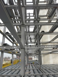
[top]Tall commercial buildings
In London, a number of major towers have taken steel to new frontiers. Two of these are the Swiss Re building and the Broadgate Tower.
London’s Swiss Re building by Normal Foster is now an iconic building, and consists of a diagrid assembly of inclined members and welded nodes to form the complex curved shape in two directions. The steel structure was therefore a key part of the architectural concept.
Broadgate Tower was unusual in that it was a 35 storey super-structure constructed over the railway lines to London’s Liverpool Street station, and therefore the need to minimise the weight of the structure on its inclined supports and on the foundations was important to the design solution. This project was completed without disrupting the day to day operation of this major London railway hub.
- Tall steel-framed commerical buildings
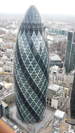
Swiss Re building – an iconic building on London’s skyline
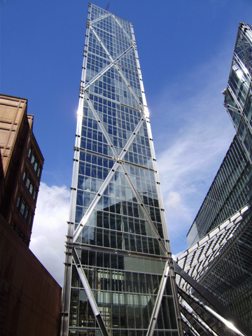
Broadgate Tower London spans over railway lines


The requirements for access to the upper levels of tall buildings and for overall stability mean that the core area is a high proportion of the plan area and is generally located centrally on plan. The office space wraps around the core, and from a functional point of view, this space should be as flexible as possible. The main beams therefore radiate from the core and are supported on perimeter columns. The provision of natural lighting tends to mean that the width of the office space is limited to about 15m. Services emanate from the core and are distributed through openings in the structure.
The nature of the construction is that the core is generally in slip formed reinforced concrete. The core construction progresses a few floors above the steel construction, which is faster and so its progress is limited by the construction of the core.
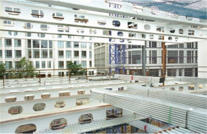
[top]Commercial buildings with atria
Larger commercial buildings are often designed around an atrium, which provides natural lighting and circulation space for the offices around it. There are many examples of this form of construction, such as in Mid-City Place, 7 More London and Tower Place in London. The plan form of 7 More London (a BREEAM Outstanding building) is shown below.
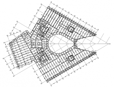

The area of the building on plan tends to be large (over 1,000m2 per floor) and the atrium is often located centrally, or may form part of an extended entrance area. The atrium is designed as part of the whole building energy and lighting strategy, and also provides the safe means of escape in fire; therefore smoke control in the atrium is a crucial part of the design solution. For a building layout point of view, the commercial space is typically 15 to 18m wide around the atrium and the cores are located at positions dictated by means of escape in fire. Generally, a minimum of two cores, and often as many as four separate cores are required on plan in buildings with atria. The simplified plan form of an office building with a central atrium is shown.


The optimum use of space means that there is benefit in designing the structure to span from the atrium to the façade columns, which are located typically on a 6 to 8m grid around the perimeter of the building. The service routes from the cores can be relatively long, which means that the duct sizes can be large when distributed from the core. In this area, the use of shorter span beams with large rectangular openings may be more practical.


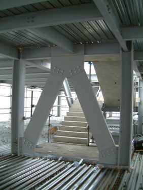
The steel elements used in the atrium are generally in the form of hollow sections and tension ties, which are often designed architecturally to emphasise the high quality of the public space that is created.
Tower Place in London combines a wide range of steel members, including hollow sections in the 6 storey high entrance atrium, as shown.

[top]Mixed use commercial buildings
Mixed-use buildings may take the form of:
- Office buildings over car parking
- Office building over retail space
- Residential building over office or retail space
These mixed use buildings pose particular questions in terms of the building layout in terms of:
- Compatibility of column locations and planning grids
- Independent access to the different space uses
- Loading requirements of the different space uses
- Fire safety and fire resistance requirements
- Servicing and service routing through the different occupancies
- Acoustic issues and, in some cases, control of vibrations.
Mixed use buildings can be designed so that the column grid is compatible with the different uses. For buildings over car parking, the column layout has to be compatible with the space below. A 7.5m column grid in one direction allows for 3 car spaces, and in the other direction, the column spans are typically 5m, 7m and 5m, or combinations of these spans. A clear span of 17m is therefore the optimum for both the car parking and commercial space, and this can be achieved in steel construction.
Shallow floor systems, such as Ultra Shallow Floor Beams (USFB), may be used for basement car parking and this has the potential to reduce the basement depth.
Alternatively in residential buildings over commercial or retail areas, a steel transfer structure may be designed above the office or retail space, so that the residential space may be configured optimally. The transfer structure is designed to support the weight of the building above and so the use of a lightweight steel structure above leads to direct benefits in terms of the size and complexity of the transfer structure. This is an important market for steel construction.
[top]Commercial buildings in suburban areas
In-out-of-town or suburban areas, commercial buildings are often smaller (typically 2 to 4 storeys) than in city centres and are less constrained by the buildings around them. In this type of building, natural ventilation is often preferred to air–conditioning for environmental and economic reasons. Therefore the depth of the floor plate is limited to around 13.5m to permit good natural lighting and ventilation. Conventionally, this is achieved using an off-centre line of columns at 7.5m and 6m from either facade to create a 1.5m central corridor. Increasingly, a 13.5m span structure is found to be more economic in terms of building and operational cost, as it leads to more efficient partitioning of the space. A simplified plan form is shown.


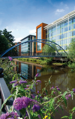
Many buildings on science parks or out-of-town-areas are designed for a range of space uses and often the energy efficiency strategy is based on effective shading and air movement to improve ventilation and to avoid over-heating. Examples include the Arup campus building and Wessex Waters HQ in Bath.
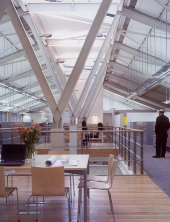
Arup Campus, Solihull
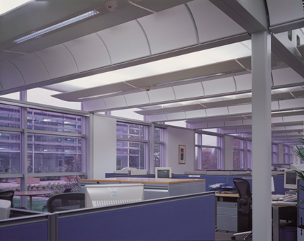
Exposed floor structure at Wessex Water offices, Bath


Foundations tend to be simpler than in city centre projects. Solutions such as pad footings under columns and basements are not common unless used to house services plant. In that case, the basement does not usually extend over the whole plan area of the building. Services are also generally simpler than in city centre projects, and a wide range of façade systems are used depending on planning requirements, ranging from ground supported brickwork to curtain walling systems, .
[top]Structural options in commercial buildings
Main articles: Braced frames, Continuous frames, Composite construction, Floor systems, Long-span beams
[top]Braced frames
The majority of structural systems used in office construction are braced by one of two methods;
- Steel bracing, generally in the form of cross-flat plates or hollow sections that are located in the façade walls, or in internal separating walls, or around service areas and stairs.
- Concrete or steel plated cores that enclose the stairs and lifts, service risers, toilets etc.
The choice of this system depends on the form and scale of the buildings. In most buildings up to 6 storeys high, steel bracing is preferred, although its location is strongly influenced by the layout of the building. V or K bracing using tubular sections is often preferred as it is more compact and can be arranged around windows and doors in some cases. X flat bracing is preferred for use in brickwork as it can be located in the cavity between the leaves of the brickwork.
For taller buildings, concrete cores are more efficient and they can either be constructed floor by floor using conventional formwork, or slip-formed continuously. The relative economics is dictated by speed of construction, and slip forming is often used on tall buildings (see Commercial buildings with atria). Steel plated or composite cores are also used where there is need to minimise the space occupied by the core and where it can be constructed in parallel with the steel framework.
The structural design of the steel frame is therefore based on the use of simple shear resisting connections for both the beam to column and beam to beam connections.
Lateral stability system overview
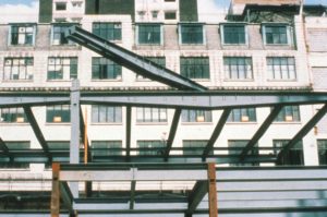
[top]Continuous frames

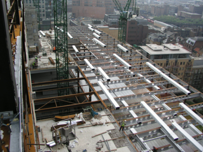
Continuous frames achieve continuity of the beams either by design of the steel structure so that they are multi-span, or by use of moment-resisting connections. In the Palestra building, the primary beams were arranged in pairs either side of the tubular columns, and the beams were continuous across the building, being spliced only at the quarter span positions from the internal columns where bending moment were low. In that way, the beams are stiffer due to their continuity than the equivalent simply supported beam and so that depth can be reduced. A view of the building during construction is shown.
In buildings up to four storeys in height, it may be economic to design the steel structure as a sway frame to resist lateral loads applied to the building. The connections between the beams and the columns are made moment-resisting by use of extended end plate connections. The columns may be heavier than in simply supported design, but the beams can be lighter, and bracing is eliminated. This may be advantageous in low-rise buildings with highly glazed facades.
[top]Composite construction

Composite construction consists of downstand I-section steel beams with shear connectors (studs) welded to the top flange to enable the beam to act compositely with an in-situ composite floor slab.
The composite slab comprises profiled decking of various shapes that span 3m to 4m between secondary beams. Floor slabs are typically 130mm to 150mm deep, depending on the deck height. The shear connectors are normally site welded through the steel decking which then supports the wet weight of the concrete and construction loading and later acts compositely with the concrete.
The secondary beams in the floor grid support the composite slab and are supported by primary beams. These beams are usually designed as composite, and in the optimum floor grid the secondaries span around 50% longer than the primaries, so that they are of similar depth. Therefore, 6m x 9m and 7.5m x 12m column grids are commonly used in composite construction.
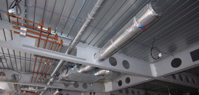
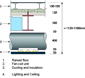
Heating and ventilation units can be positioned between beams, but ducts will generally pass below downstand beams. Typically, for a 7.5m x 6m floor grid, the overall floor zone is 1100mm to 1200mm allowing for a 150mm raised floor and 400mm deep air conditioning ducts below the beams. This floor depth may reduce to 700mm in the case without air conditioning services. A typical example of a composite beam with service routing is shown.
[top]Long span systems
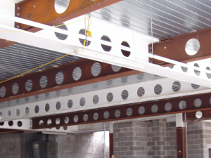
[top]Beams with web openings
Long span composite beams are often designed with large web openings to facilitate integration of services, as shown. In long-span construction, grids are generally arranged so that the long span secondary beams are supported by shorter span primary beams. It may be economic to design long span primary beams that support shorter span secondary beams, when considering the use of cellular and fabricated sections.
The two options are:
- Long span secondary beams: 10m to 15m span at 3m to 4m spacing.
- Long span primary beams: 9m to 12m span at 6m to 9m spacing.
Service openings can be circular, elongated or rectangular in shape, and can be up to 70% of the beam depth. They can have a length/depth ratio typically of up to 3.5. Web stiffeners may be required around large openings.
Elongated or rectangular openings should be located in areas of low shear, e.g. in the middle third of the span for uniformly loaded beams. Isolated openings can be reinforced by horizontal stiffeners, as shown, which increases their resistance to shear by local bending around the openings (Vierendeel bending).


[top]Cellular beams

Cellular beams are beams with openings regular spacing along their length. The beams are made by cutting and re welding hot rolled steel sections. Openings, or ‘cells’, are normally circular, which are ideally suited to circular ducts, but can be elongated, rectangular or hexagonal.
The full range of hot rolled steel section sizes is available from which to choose the sizes of the top and bottom chords. For composite design, the top chord is generally chosen as a lighter section than the bottom chord.
Cellular beams are generally arranged as long span secondary beams, supporting the floor slab directly, as shown.
[top]Fabricated beams

Fabricated beams are made from three steel plates whose sizes can be selected for the particular loading case. Openings for services can be cut into the web, and the sizes of the openings can be designed depending on the forces acting at a point in the span. An example of fabricated beams with circular elongated-circular and rectangular openings is shown.
One of the advantages of the use of fabricated beams is that they can be designed to support relatively heavy loads when used as long spanning primary beams.
[top]Other types of long span beams

Tapered beams can be designed so that the depth of the beam is tailored to broadly match the bending moment applied to it. In this way, the depth of the tapered section is normally in the form of a single linear variation from mid-span to the supports, and the minimum depth at the supports is sized only to provide the required shear resistance. Relatively wide zones for services are provided near to the supports. An example of tapered beams is shown.
[top]Shallow floor beams

(Image courtesy of Kloeckner Westok)
Shallow floor beams are typically asymmetric steel beams with a wider bottom than top flange, which enables the slab to sit on the upper surface of the bottom flange with adequate bearing, rather than the upper surface of the top flange as found with downstand beams. The floor slab may be in the form of a precast concrete slab or a composite slab with metal decking (either shallow or deep decking may be used).
A number of shallow floor systems are available, including Ultra Shallow Floor Beams (USFB) from Kloeckner Westok, and ArcelorMittal's Slim Floor.
Kloeckner Westok’s USFB system comprises a shallow and asymmetric Westok cellular beam with reinforcement placed through the cells to anchor the slab to the beam. The USFB is manufactured from standard rolled sections, and is available in increments of 1mm depth. They are typically 150-300mm deep and are sized and designed using Westok’s freely available Cellbeam software package based on each individual project requirements and floor grids etc. USFBs can economically span up to 10m with structural depths that compare very favourably with R.C. flat slabs. As such, they are popular in many sectors including multi-storey office buildings.
[top]Floor systems


The three generic forms of flooring systems which are most commonly used in steel framed office buildings are:
- Shallow composite slabs using steel deck profiles typically of 50 to 80mm depth. The slab depth is usually 130 to 160mm, depending on the deck depth and fire insulation requirement. Typical spans are 2.5 to 4.5m depending on the deck spanning capabilities.
- Deep composite slabs using steel decking of 210 to 225mm depth in which the typical slab depth is 280 to 350mm. Deep composite slabs are mainly used in shallow floor construction for spans of 5 to 9m.
- Precast concrete slabs generally in the form of hollow-core units of 150 to 300mm depth with an in-situ concrete slab of 60 to 100 mm depth. Typical spans are 5 to 10m depending on the depth of the hollow-core units.
Composite floors using shallow decking
The generic shallow deck profiles used in composite floors are illustrated. During the construction stage, and prior to composite action of the decking and concrete being fully achieved in the normal stage, the decking alone will need to support the load due to wet concrete and construction live loads. Pattern loading due to the construction sequence should also be considered during the construction stage. During construction, propping to the decking may allow longer spans to be achieved in the normal stage. Propping may be seen as impacting on access and programme and to whether or not to prop the decking should be discussed early in the design process. Props should be left in place until the concrete has reached its design strength.
Modern composite slabs contain re-entrant portions which facilitate attachment of wires for suspended services and ceiling. Trapezoidal profiles are based on a 300mm rib spacing, and often the cross-section is highly stiffened to improve its bending and composite properties.
Reinforcement in the slab provides up to 120 minutes fire resistance, but for longer periods of fire resistance (which are unusual in the UK), reinforcing bars may be placed in the deck ribs.
Steel decking is installed by craning onto the primary steelwork in bundles and usually man-handling into position. A fall arrest system is installed immediately after the steelwork is erected and before the decking is placed.
Completed and decked floors may be used as a safe working platform for subsequent installation of steelwork. For this reason, the upper floor in any group of floors (usually three floor levels) is often concreted first.
Composite floors using deep decking
The cross-section through a composite floor slab using deep decking is shown below.


The deep decking is supported on end diaphragms which provide stability to the web of the decking and also prevents loss of concrete when it is poured on the decking. Reinforcing bars of 12 to 20mm are placed in the deck ribs, mainly for fire resistance purposes, and mesh reinforcement is placed in the topping. Un-propped spans of up to 6m can be achieved. Shallow floor systems are used in many sectors and often in mixed-use buildings and in basements or car parks to multi-storey buildings where minimising of the floor depth has economic value.
Precast concrete slabs
Precast concrete slabs are proprietary products that are manufactured in standard depths and widths. They are pre-stressed to increase their spanning capabilities and stiffness which also means that they have some negative curvature when unloaded. Hollow-core slabs have regular circular openings and in some cases, elongated openings along their length to reduce their weight. Precast slabs are widely used in smaller offices, but less so in large building projects. They are also used in Shallow floor systems .
[top]Key issues in the design of commercial buildings
Main articles: Cost of structural steelwork, Cost planning through design stages, Cost comparison studies, Operational carbon, Thermal mass, Target Zero, Service integration, Fire and steel construction, Acoustics, Floor vibrations, Fabrication, Construction
[top]Procurement
Procurement in the commercial building sector is often different from other sectors, depending on whether the building is a speculative development, or is intended for a single client.
In major city centre projects, the concept of ‘shell and core’ was established in the late-1980s. In this ‘fast track’ approach to design and procurement, the main fabric of the building is let as the first stage contract, and then a second stage fit-out contract is managed by the team acting on the tenant’s behalf. This two stage process means that the hand-over between architects and contractors in the two stages has to be carefully managed to avoid division of responsibilities. The second stage fit-out can involve as little as internal partitioning and decoration, but can include complex installation of services and specialist IT systems.
This lead to the concept of ‘loose fit’ structures giving maximum flexibility in servicing and internal space use, for which long span steel and composite construction is ideally suited.
For single clients, the procurement process is more straightforward in that the client brief will define the functional and spatial requirements, and then the whole construction process falls under one contract. There are three generic contractual systems that may be used for commercial buildings depending on their scale and the type of client:
- Traditional contracts, in which the contractor is appointed by competitive tender based on detailed drawings and specifications. The architect often takes a more formal role in project management on behalf of the client.
- Design and build contracts, in which the contractor bids for the project, based on a more general scope of work, and is involved in much of the detailed design work. The architect involved in the early stages of the design development with the client is often ‘novated’ to the design and build contractor.
- In management contracts, the management contractor organises the project as a series of relatively large ‘packages’ and is paid a fee by the client. In this process, the supply of the steel frames and floors is a key package, as is the detailed design and supply of the façade system etc.
For large commercial projects, management contracts are efficient in that the management fee are offset by the gains that are possible by competitive tendering of the various ‘packages’ of work. Smaller commercial building projects are often procured by ‘design and build’.
A recent important innovation is that of Building Information Management (BIM) systems in which the design team, contractor and specialist suppliers share in a common design and drawing system so that interface and scheduling problems are minimised. The BIM system is generally managed and controlled by the main contractor and requires an early involvement of specialist suppliers in the design process. Image does not exist
[top]Client requirements in multi-storey office buildings

Client requirements have an important effect on the planning of modern commercial buildings, and influence how the benefits of steel construction may be achieved in practice. These requirements may be defined by the physical aspects of the building, floor loadings, and the building services and fire safety strategy. The British Council for Offices has produced specifications and guidance on the design parameters that are relevant to this sector.
The floor to floor zone is a key design parameter, which is influenced by planning requirements, such as overall building height, natural lighting, aesthetics , and other aspects.
Examples of general client requirements in office buildings are:
- Occupation density 1 person per 10 to 15m2
- Useable floor area :Total area 80 to 90% typically
- Floor to floor zone 3.6 to 4.2m
- Floor to ceiling zone 2.7 to 3m typically
- Planning module 1.2 to 1.5m
- Imposed loading 2.5 to 5kN/m2
- Fire resistance 30 to 120 minutes.
[top]Building economics
The economics of most commercial buildings is that the client or developer expects to re-coup the investment in 10 to 15 years, and so there is a premium for early completion and future adaptability to meet a range of functional requirements. Although these economic benefits cannot necessarily be achieved to the same degree on all projects, it is often found that in combination, these tangible savings can represent 2 to 5% of the construction cost and 2 to 3% of the operational cost of a modern commercial building.
It is estimated that the total cost of running a building during a 60 year design life may be 3 to 5 times the initial construction cost. Major components of the longer term operational costs include:
- Direct running costs of lighting, heating and air conditioning etc
- Refurbishing the interior, such as minor redecoration every 3 to 5 years, and major re-fitting every 10 to 20 years
- Replacing the services, approximately every 15 to 20 years
- Possibly re-cladding the building after 25 to 40 years.
The energy performance of office buildings is a major factor in modern design because lighting, heating and cooling are major users of energy, generally in the form of electricity. Building services can be responsible for 60% of the total energy use of the building.
Under Part L of the Building Regulations, modern commercial building projects are required to meet increasingly tough operation carbon emissions targets. Also, since 2008, all commercial properties are also required to have an Energy Performance Certificate. Energy performance therefore strongly influences, and can impose restrictions on, how the commercial buildings are designed.
The as-built cost of a modern commercial building which may involve office, retail, and public space varies greatly depending on its complexity and location. As a guide, the total build cost can be as high as £3,500 per m2 of gross floor area in major city centre projects which often have complex sub-structure and temporary works costs. For smaller out of town projects, the median build cost is around £1,800 per m2 of gross floor area. The costs of the structural parts of the building are typically only 10 to 15% of the total cost but have an important effect on the economies that can be achieved in the other parts of the building and in speed of construction.
Specific guidance on the cost planning of multi-storey commercial buildings is available.
A breakdown of construction costs for a typical office building is approximately as below:
- Foundations 5 to 15%
- Super-structure and floors 10 to 12%
- Cladding and roofing 15 to 25%
- Services (mechanical , electrical & lifts) 20 to 25%
- Services (sanitation and water) 5 to 8%
- Finishes, partitions and fitments 10 to 20%
- Site management (preliminaries) 12 to 18%
Preliminaries represent the costs of the site management and on-site facilities, including hire of cranes, storage space and equipment. Site preliminaries can vary with the scale of the project, and a figure of 15% of the total cost is often allowed for site-intensive construction reducing to 10% for projects involving higher levels of off-site prefabrication, such as steel construction.
The results of a recent independent cost comparison study of multi-storey commercial buildings is also available.
[top]Construction programme

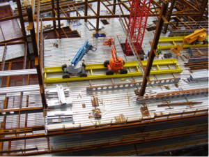
Composite construction has become the dominant form of construction in the commercial building sector because it provides long span, stiff floors and because it is a rapid form of construction. The steel erection programme is dependent on the number of tower cranes employed and use of long span beams requires fewer albeit heavier components, and therefore speeds up the whole process. Bundles of decking are placed on the steel beams, as shown. The construction programme for a typical steel framed office building of 6 storeys height and about 4000 m2 floor are as shown . The placing of decking follows the steelwork installation and the concreting operation can take place one floor below. Through deck welding of the shear connectors also speeds up the process. Having concreted the floor without any temporary propping, the next day it acts as working platform for following trades such as servicing, and placement of infill walling, whilst the upper floors are being installed.


This ability to start these ‘follow-on’ activities early in the construction process is responsible for an overall saving in construction time of between 20 and 30% relative to site-intensive construction. This can lead to considerable cost savings.
The steelwork package is a single point of procurement and often includes decking and through deck welding of shear connectors, and in some cases, concreting. Detailing is carried out by the steelwork contractor and all design information is integrated into a client’s Building Information System. This ensures that cladding and services are integrated with respect to the steelwork design.
Increasingly, structures are constructed on poor ground conditions, or on ‘brownfield’ sites (land previously built upon). In city centres, major services and underground works, such as tunnels, often influence the chosen solution.
Poor ground conditions tend to require a lightweight solution involving fewer foundations. This often necessitates long span for the superstructure. A steel structure is up to 50% lighter than an equivalent concrete structure.
A confined site can place constraints on choice of the structural scheme, for example the size of the elements that can be delivered and erected. Composite floors are often preferred in these cases.

Cranes
Multi-storey structures are often erected using a tower crane. The number of cranes required on a project is influenced by:
- The site ‘footprint’ - can cranes provide a sensible coverage of the building site, including off-loading of materials?
- The size of the project - can more than one crane be utilised effectively?
- Commercial decisions on cost and programme benefits.
Installation rates are dominated by ‘hook time’ - the time connected to the crane. Fewer pieces to install, or use of more cranes, will reduce the construction programme. Smaller inner city sites are often served by a single tower crane that is used by all trades.
These competing demands can slow overall progress of the steelwork erection. For larger projects, it is an important requirement to enable other trades to commence their activities as the steelwork installation progresses.
Installation rates
As an indication, an installation rate of between 20 and 30 pieces of steel per day is reasonable for most commercial building projects. For average weights of the components, this equates to approximately 10 to 12 tonnes of steel per day. Therefore there is a benefit in using fewer, longer spanning beams, which can reduce the number of components by up to 25%.
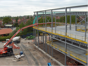

Concreting rates
Concrete in modern steel-framed buildings is placed by pump using concrete mixes designed for this purpose. Concreting rates of over 2,000m2 per day are possible (approximately 250 m3 of concrete). This means that a whole floor can be concreted without construction joints.
An accurate concrete level is achieved in un-propped composite construction and the light steel edge trim ensures that the level is maintained at the facades and at large openings. Where required, construction joints are generally made along the lines of the beams.
The rate of gain of strength of concrete is such that the recently completed composite floor can be used for access the next day, and for storage of materials and equipment after 7 days.
[top]Sustainability
In the context of modern office buildings, the principal sustainability issues to address include how to minimise operational energy use, particularly in the heating, cooling and lighting systems, how to achieve high BREEAM ratings and any specific planning requirements.
[top]Operational energy use in offices
The breakdown in operational carbon emissions by energy use in a typical multi-storey office building is shown. For a definition of unregulated energy, click here.
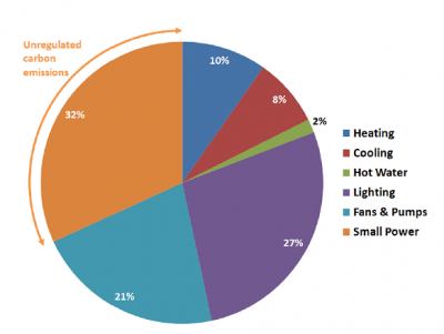

Lighting is the most significant regulated energy demand, accounting for around a quarter of the total operational carbon emissions. Consequently efficient lighting systems coupled with optimum glazing and solar shading design are important in delivering operational carbon reductions. The complexity of the interaction between the glazing, lighting, heating and cooling in large office buildings requires detailed dynamic thermal modelling to develop an optimum low carbon solution.
As shown, the proportion of operational carbon emissions from heating (10%) and cooling (8%) are very similar and therefore, energy efficiency measures which impact this heating/cooling balance of the building are difficult to optimise. Measures to reduce heat loss or increase solar gains, reduce emissions from space heating but increase those from cooling. Similarly measures that increase heat loss or reduce solar gains, increase emissions from space heating and reduce those from cooling.
In many new commercial building projects, it is required to provide a proportion of on-site energy generation from renewable sources (the so-called Merton rule). This is normally about 10% of the buildings energy use and is generally provided by means of photovoltaic panels, ground sourced heating and cooling (e.g. by thermal piles) and, in some more exposed locations, building mounted wind turbines.
Thermal insulation of the building envelope is traditionally the architect’s responsibility, but the structural engineer must be involved in the development of appropriate details. For example, supporting systems for cladding should be addressed, and steel members that penetrate the insulation, such as balcony supports, should be detailed to minimise the effects of thermal bridging.
City centre office buildings face several challenges with respect to increasingly onerous low and zero operational carbon emissions targets. This is because there are limited opportunities to:
- Include some low and zero carbon technologies, for example limited roof area for solar technologies, shading by neighbouring buildings affecting the viability of both solar and wind technologies and restricted access for biomass deliveries, etc.
- Naturally ventilate the building, mainly due to security, acoustic and air quality issues associated with inner city locations
- Optimise orientation due to tighter site constraints than less restricted suburban and rural sites.
The Target Zero project provides in depth guidance about how to achieve low and zero operational carbon targets in commercial office buildings.
[top]BREEAM for office buildings
The BREEAM environmental assessment scheme provides a method for quantifying the environmental performance of buildings. Although the scheme is voluntary, many commercial sector clients are responding to demand and adopting BREEAM to deliver buildings which are low energy, sustainable and future-proofed.
Results from the Target Zero programme suggest that for city centre office buildings, the increase in capital cost (from a Part L 2006 compliant base case) to achieve the following BREEAM (2008) ratings:
- 0.17% to achieve BREEAM ‘Very Good’
- 0.77% to achieve BREEAM ‘Excellent’
- 9.83% to achieve BREEAM ‘Outstanding’.

[top]Loading for offices
Loading on structures is covered in BS EN 1991: Eurocode 1. Actions on structures. Recommended values for imposed loads are given in BS EN 1991-1-1[1] and for fire loads in BS EN 1991-1-2[2]. Snow loads are given in BS EN 1991-1-3[3] and wind actions in BS EN 1991-1-4[4]. Actions during construction can be found in BS EN 1991-1-6[5].
Design checks are made at the ultimate limit state (ULS) and the serviceability limit state (SLS).
Wind loads are generally transferred from the façades via the slab to the concrete core, which also encloses the staircases and elevators. Bracing systems located in the façades or rigid frame construction may be considered for buildings of up to six storeys height.
Long-span composite beams are often pre-cambered in order to offset the deflection of the steel beam under self-weight loads. Imposed loads are resisted by the stiffer composite section. The final deflection is a combination of the construction stage and in service deflection.
As well as the self-weight of the floors and frame, an additional load of 0.7 kN/m2 should be considered for raised floors, ceilings and building services equipment.
Imposed loading is the variable loading that is applied to the structure and includes loads due to occupants, equipment, furniture and movable partitions, and also snow on roofs. The magnitude of the imposed loading varies according to the use of any specific floor area being considered - different values are applied for a plant room or storage area, for example.
EN 1991-1-1[1] presents minimum imposed floor loads for different building uses. For offices, the design imposed loading is typically 3kN/m2. In addition, up to 1kN/m2 may be added for movable partitions. For storage areas, a higher value of 5kN/m2 may be used. Often, an imposed load of 5kN/m2 is specified in speculative offices to allow for a wide range of client uses.
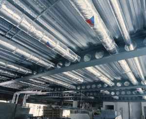
[top]Services and service integration
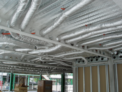

Despite the move to greater energy efficiency in buildings and, where possible, the use of natural ventilation strategies, most large commercial buildings will continue to require some form of mechanical ventilation and air conditioning. The provision for such systems is important as it affects the layout and type of members chosen in the structure. By integrating services within the structural depth of floors, the overall height of the building can be minimised.
The basic decision to either integrate the services within the structural depth or to suspend the services below the structure affects the choice of structure, the fire protection system, the cladding details and the overall building height. There are two general approaches:
- Minimise the structural zone so that services pass underneath. This is the approach used in shallow floor construction in which the structural zone is typicaly only 300mm.
- Distribute services within the structural zone by provision of large openings within the depth of the steel beams. This is best achieved in long span construction where the beam size is dictated by structural requirements and large openings can be provided in the web.
The distribution of services emanates from a vertical riser generally at a core, and so the location of the cores in relation to the structural arrangement is very important to the effective distribution of services. In some systems, the local temperature control is by a local unit which can be located between the steel beams. In others, these local controls are located in the core for ease of maintenance and the ducts are distributed through multiple circular openings.
There are three ways of providing comfort cooling, by:
- Variable Air Volume (VAV) systems in which air is delivered centrally and controlled locally by the VAV or VRV box, which is suspended below the composite floor slab
- Fan-coil units (FCUs) in which water is delivered to the units and delivered air is chilled or heated locally. These systems require distribution of water pipes as well as air ducting but can be most efficient.
- Chilled beams or chilled ceilings which provide radiant cooling to the space. Chilled beams are linear elements which can allow for air to be delivered through them. Chilled beams are flat elements and often require separate fresh air supply.
VAV systems are often used in buildings with single owner occupiers, because of their lower running costs. FCU systems are often used in speculative commercial buildings because of their lower capital costs.
Generally, a zone of 450 mm permits services to be suspended below the structure. An additional 150-200mm is usually allowed for fire protection, ceiling and lighting units and a nominal structural deflection (25mm). Terminal units (FCU or VAV units) are located between the steel beams where space is available.
A 150 to 200mm deep raised access floor is generally provided in offices for distribution of telecommunications services. Some under floor systems provide for distribution of conditioned air through a deeper raised floor acting as a plenum.
[top]Fire protection

The UK benefits from a competitive and efficient structural fire protection sector which delivers excellent value at low cost. Modern fire protection is dominated by thin film intumescent coatings with boards and sprays also having significant market share.
It is possible to reduce the costs of fire protecion further in some buildings using an engineered approach. Fire engineering is widely used in steel buildings, especially those that are large, complex or unusual in any way. It is now recogised that this may be the only way to guarantee that such buildings are safe in fire and that the more prescriptive approaches may be inadequate. See here for more on this.
An engineered approach to fire precautions in buildings can deliver significant economies in the cost of fire precautions in buildings, generally by demonstrating that fire ratings can be reduced and some steelwork may be left unprotected but engineered approaches can also offer economic solutions to fire precautions in buildings across many areas.
[top]Floor vibrations
Floor vibrations are caused by the activities in the building, such as fast walking, impact or machine operation etc. In offices, the level of vibration that is acceptable is influenced by the activities that are being performed. A busy office may not require vibration limits as strict as those in a hospital or laboratory in which delicate tasks are being performed. The requirements are expressed in terms of a Response factor which is a multiple of the base perceptibility to BS 6472-1[6] (normally a factor of 4 to 12 for offices).
The control of floor vibrations is achieved by two methods:
- Maximising the stiffness of the floor so that its fundamental vibration frequency (natural frequency) exceeds the likely vibration excitation (normally walking) by a factor of 3. For a footfall of two steps per second, a natural frequency of more than 6Hz generally ensures minimal vibration response to the third harmonic of footfall excitation. For very lightweight floors, this limit is increased to 8Hz. Whilst this simple criterion is generally acceptable for busy workplaces, it is not appropriate for quieter areas of buildings, where vibrations may be more perceptible.

- A more appropriate method is response factor approach which is based on the level of the vibration, measured in terms of acceleration. Higher accelerations indicate a dynamic response that is more noticeable to the occupants. This approach is particularly suitable for floors where control of vibrations is required, such as in hospitals, or in floors where the natural frequency is between 4 and 6Hz.
In practice, response is reduced (i.e. vibration is less noticeable) by increasing the mass participating in the motion. It is found that long span floors have relatively low response factors (compared to shorter spans) despite their lower natural frequency because the participating mass of the whole floor plate is relatively high. This is contrary to ideas based on natural frequency alone.
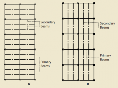
Beam layout is often important, as longer continuous lines of secondary beams in composite construction result in lower response factors, because more mass participates in the motion. Two possible arrangements of beams are shown. The dynamic response for arrangement (B) will be lower (less noticeable) than arrangement (A), as the participating mass is increased in arrangement (B).
Damping reduces the dynamic response of a floor. Floor response is decreased by partitions at right angles to the main vibrating elements (usually the secondary beams), although the inclusion of this factor in design can prove unreliable, as the exact effect of partitions is difficult to determine. Bare floors, particularly during construction, are likely to feel more ‘lively’ than when occupied because the fit-out of a building increases damping by as much as a factor of 3.
Further information on floor vibrations is available here and in SCI P354. The Steel Construction: Floor Vibration publication is also relevant, and a useful web-based Floor response calculator is also available to swiftly evaluate the vibration response of floors.
[top]Acoustic performance
The acoustic requirements of commercial buildings are such that the floors provide an vertical acoustic separating function, and the internal walls between individual occupancies provide a separating and often a fire resisting function. Floors are required to provide a minimum level of acoustic attenuation (sound reduction), but this requirement is normally easily satisfied by the depth of composite floors that are also designed for a minimum of 60 minutes fire resistance. A raised access floor and suspended ceiling provides some additional benefit, but are not generally taken into account in terms of their acoustic attenuation.
Some commercial buildings next to railway lines or busy highways for example, are designed for high levels of sound reduction to external noise, and this is often achieved in the facade design rather than any modification to the primary structure.
Separating walls are often in the form of double skin light steel walls, and in steel framed construction, these walls should be aligned with beams so that detailing required to prevent acoustic ‘flanking‘ losses is easier.
The SCI has developed an acoustic performance prediction tool for floors and separating walls to assist designers and architects.
[top]Health and safety

Modern multi-storey steel construction as used in office buildings ensures a high level of safety during construction by:
- Safety barriers and edge protection can be provided as part of the steelwork package
- Steelwork can be installed from mobile platforms (MEWPS)
- Decking is delivered cut to exact length so that little cutting is required on site.
- Decking is installed from the previously decked areas by installers who are connected to lanyards connected to the steel columns, and often inflatable bags are used on the levels below.
- The decking acts a safe working platform before the concrete is cast, and no temporary propping is required.
- Light steel infill walls and modern curtain walling are installed from inside the building.
- Materials handling is minimised and no or little waste is created.
[top]Corrosion protection
In office buildings that are well heated and maintained, steel frames do not generally require protection against corrosion because long term measurements have shown that any deterioration of the steel components over time is non-existent or negligible. Exceptions may be made for steelwork in ‘cold’ roofs or in some facade systems where the steel elements partially bridge the insulating or weather resisting layers.
Steel decking and light steel infill walls use galvanized steel and so are protected against corrosion in an internal atmosphere. In infill walls, the light steel components, which are also galvanized, are weather protected by the cladding system and by the external insulation.
[top]Fabrication and construction
Modern steel construction in multi-storey buildings includes many features designed to optimise the fabrication process, to increase the speed of construction, and to ensure a high level of safety during construction. Some features of modern steel construction relevant to multi-storey commercial buildings are as follows;

- Primary beams that support secondary beams and connect to the columns are designed with full depth end plate connections to provide for a high level of robustness
- Secondary beams can be connected to the primary beams using extended fin plates to avoid notching of the incoming beams
- Beam depths can be minimised by designing the secondary beams to span the longer distance in the floor grid
- Cellular beams formed by cutting and re-welding rolled sections, or by cutting openings in the webs of fabricated beams provide for efficient integration of services
- Columns are installed in 2 or 3 storey-high lengths with splices at approximately 1m above the floor level
- Steel bracing can be located around cores or in strategic locations in the façade and X, K or W bracing can be designed efficiently using hollow sections.
- Steel beams and columns can be delivered with thin film intumescent coating applied off-site so that fire protection is taken off the citical path, on-site trades are minimised, weather dependency is reduced etc.
- Safety barriers and edge protection can be pre-fixed to the steel members or attached on site in preformed pockets etc.
- In tall buildings, steelwork can be installed from mobile platforms (MEWPS) that are lifted into place and run long rails that are attached to the tops of the beams.
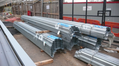
- Decking is delivered cut to exact length and uniquely marked so that it can be installed rapidly with no waste - see right.
- Light steel infill walls can be installed efficiently and can be fitted around bracing members.
[top]Connections
Main articles: Facades & interfaces, Simple connections, Moment resisting connections
Connections between steel beams and columns in multi-storey office buildings are generally designed as shear resisting simple connections, and are of the following forms:
- End plate connections of the beams to the columns
- Fin plate connections or partial depth end plate connections of the secondary beams to the primary beams
- Column splice connections normally ever second or third floor, so that the column can be reduced in size at the upper levels of the building where loads are less.
- Column base connections to foundations
- Bracing connections to the columns that are dependent on the type of bracing e.g. cross-flats use shear resisting bolts to fin plates welded to the columns
Moment resisting connections may be used for buildings up to 4 storeys height in which the connections are in the form of extended end plate that are capable of resisting relatively high moments and are effectively rigid.
Where overall stability is provided by a concrete core, the connection between the steel frame and the concrete core requires special consideration. Guidance for the design of cast-in steel plates for connecting structural steel beams to concrete core walls is available in SCI-P416.
[top]Typical details
The types of connections details that are used in commercial buildings reflect the type of members that are connected and the magnitude of the loads that are resisted. For example, connections to columns are made by beams that are generally at right angles to the column, and so consist of connections to the column flange and to the columns web. Bolted rather than welded connections are used and the standard size of bolt is 20mm diameter, grade 8.8.
A flush end plate welded also to the flanges as well as the web is typically used. 4, 6 or 8 bolts acting in shear are typical of this type of connection, and the end plate thickness to the beam is typically 10, 12 or 15mm. An extended end plate is of a similar form except the plate is extended often above and below the beam so that pairs of bolts can be added. The use of an extended end plate connection for symmetric beams is shown.
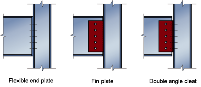
Fin plate connections are preferred by steelwork contractors for the beam to beam connections as they do not require notching of the in-coming beams but have the disadvantage that the fin plates can be long, and therefore subject to buckling. Otherwise, the secondary beams are notched where they are level with the primary beam to which they are connected. In this case, the end plate is ‘partial depth’ as it is welded to a part of the web. The various types of connections are illustrated.

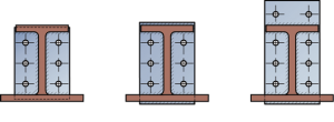
Typical full depth and extended end plate connections to asymmetric steel beams


Despite the general use of simple connections, there are often requirements for moment resisting connections which can be achieved by various types of connections. In the example shown, the design required that a column is omitted on a lower floor and a rigid connection to the discontinuous column was made by mini-haunches and 8 bolts acting in tension and shear.
Column splices may be of various forms, such as bolted splice plates or end plates, as shown. The end plates are thick enough so that they are not distorted by welding and the interfaces with the column below do not have any gaps. The bolts provide some continuity to bending, as the splice connections are made just above floor level.
Bracing in the form of flat or hollow sections are often concentrated around stairs and lift, as illustrated.
Detail used for vertical bracing in a high-rise building
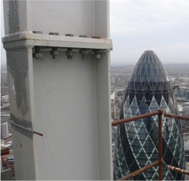
Column splice detail used in a high-rise building in London


[top]Other interfaces
The other types of connections that may be used in commercial buildings concern interfaces with cladding, lifts, foundations and specialist steelwork in the roof and atrium. Occasionally, the steelwork at the lower level is encased in concrete and tubular columns may be concrete filled where they are exposed visually. External steel work is often used for visual effect and it is connected through the façade to the internal structure. Special details have been developed to avoid cold bridging.
[top]Façade systems
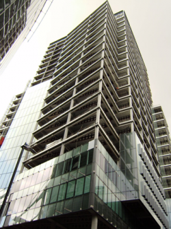

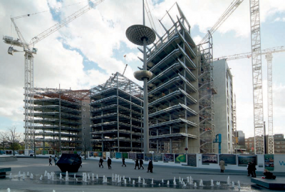
The types of facade systems that are used depend on the scale of the building and its location. For major city centre projects, curtain walling systems are generally used, and these systems assist in providing the internal climatic control. A good example of the use of unitised glazed curtain walling system is shown in the Ropemaker Place project below. Installation of the cladding started before the steelwork on the upper levels had been completed.
In smaller suburban or out of town commercial projects, more traditional cladding systems are generally used, which would include brickwork and stone veneer panels. Light steel infill walls are often used to support the cladding.
[top]Case studies
- Cefas Lowerstoft-1a.jpg
- 80 Charlotte Street-1a.jpg
- Circle Square Nos 2 and 4-1a.jpg
[top]References
- ↑ 1.0 1.1 BS EN 1991-1-1:2002 Eurocode 1. Actions on structures. General actions. Densities, self-weight, imposed loads for buildings, British Standards Institution
- ↑ BS EN 1991-1-2:2002 Eurocode 1. Actions on structures. Actions on structures exposed to fire, British Standards Institution
- ↑ BS EN 1991-1-3:2003+A1:2015 Eurocode 1. Actions on structures. General actions. Snow loads, British Standards Institution
- ↑ BS EN 1991-1-4:2005+A1:2010 Eurocode 1. Actions on structures. General actions. Wind actions, British Standards Institution
- ↑ BS EN 1991-1-6:2005, Eurocode 1. Actions on structures. General actions. Actions during execution, British Standards Institution
- ↑ BS 6472-1:2008, Guide to evaluation of human exposure to vibration in buildings. Vibration sources other than blasting, British Standards Institution
[top]Further reading
- Steel Buildings, BCSA No. 35/03, Chapter 4, Multi-Storey Buildings
- Steel Designers' Manual 7th Edition. Editors B Davison & G W Owens. The Steel Construction Institute 2012, Chapter 5, Multi-Storey Buildings
- British Council for Offices Guide to Specification, BCO, 2014
- Architectural Design in Steel – Trebilcock P and Lawson R M published by Spon, 2004
[top]Resources
- Target Zero - Guidance on the design and construction of sustainable, low carbon office buildings
- SCI P101 Interfaces - Steel Supported Glazing Systems
- SCI P166 Design of Steel Framed Buildings for Service Integration
- SCI P300 Composite Slabs and Beams using Steel Decking – Best practice for design and construction
- SCI P354 Design of Floors for Vibrations- A New Approach
- SCI P355 Design of Composite Beams with Large Web Openings
- SCI P362 Concise Eurocode for Design of Steel Buildings
- SCI P363 Steel Building Design: Design Data, 2013
A web-based interactive version of the 'Blue Book', is also available. - SCI P365 Steel Building Design: Medium Rise Braced Frames, 2009
- SCI P416 The design of cast-in plates, 2017
- Best Practice in Steel Construction: Commercial Buildings
- SCI IEP 2 Service Coordination with Structural Beams
- SCI IEP 4 Supporting Services from Steelwork
- Steel Buildings in Europe - Multi-storey buildings:
- Part 1: Architect’s guide
- Part 2: Concept design
- Part 3: Actions
- Part 4: Detailed design
- Part 5: Joint design
- Part 6: Fire Engineering
- Part 7: Model construction specification
- Part 8: Description of member resistance calculator
- Part 9: Description of simple connection resistance calculator
- Part 10: Guidance to developers of software for the design of composite beams
- SCI Acoustic performance prediction tool for separating floors and walls
- Steel Insight 4 – Cost planning of steel-framed multi-storey buildings, July 2012, Building Magazine
- Steel Insight 8 – Multi-storey commercial buildings, July 2013, Building Magazine
- Steel Insight 11 – Cost update and case studies: Commercial buildings, November 2014, Building Magazine
- Steel Insight 16 – Cost update and case studies: Commercial buildings, May 2016, Building Magazine
- Steel Construction: Floor Vibration, 2016
- Floor response calculator
- Costing Steelwork 1 – Commercial Buildings, April 2017, Building Magazine
[top]See also
- The case for steel
- Cost of structural steelwork
- Cost comparison studies
- Cost planning through design stages
- Cost planning - Multi-storey offices
- Operational carbon
- Thermal mass
- Target Zero
- Service integration
- Composite construction
- Fire and steel construction
- Floor vibrations
- Acoustics
- Health and safety
- Concept design
- Braced frames
- Continuous frames
- Floor systems
- Long-span beams
- Facades & interfaces
- Steel-supported glazed facades and roofs
- Facade supports and structural movements
- Simple connections
- Moment resisting connections