


Plan curvature in bridges
Although very many bridges follow a straight alignment from one abutment to the other, some are partly or wholly curved in plan. For road bridges, curvature may be required to optimise the layout of the carriageway. For footbridges, curvature may be employed either for a more interesting aspect for users or to enhance the appearance. Railway bridges are rarely curved in plan, since the track radius is normally so great that the deviation from straight over a span is modest and easily accommodated on a straight superstructure.
This article gives an overview of the design consequences of plan curvature for highway bridges.
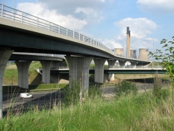
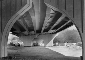
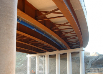
Holmfield Viaducts, A1(M) Darrington to Dishforth
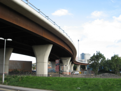
Hunslett Viaduct, Leeds
(Image courtesy of Mabey Bridge Ltd)


[top]The need for curvature in plan
Inevitably, many highway bridges carry roads that are on a curved alignment. Lower speed roads and link roads may have a radius of curvature of as low as 90m, which leads to a significant angular change in the direction of the carriageway, even over short spans, and this will have a significant effect on the design and construction of the bridge. Higher speed roads have a greater radius but then may require longer spans and the curvature will still have a significant effect on design and construction.
[top]Providing curvature in highway bridges
Horizontally curved decks can be provided by using a series of straights or the use of curved members.
A series of straight beams with angular change at discrete places may be suitable for the larger plan radii (over 300m). For a viaduct, these changes might be at 1/4 span or points of contra flexure and combined with the splices. With careful detailing, this arrangement can prove economic, but it results in a varying length of deck slab cantilever. Consequently, slab construction and final appearance will be affected.
- Curved bridge with straight girders


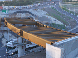
With modern fabrication equipment and associated computer modelling, curvature in plan does not pose any difficulties for the steelwork contractor. They can cut and assemble curved flanges from plate and thus provide ‘true’ curved beams.
Contractors prefer curved girders because it simplifies fixing reinforcement and formwork. And since “true” curvature generally has a much more natural appearance than a series of straights, clients’ preferences are for truly curved girders for such bridges.
A combination of horizontal and vertical curves, when viewed from certain vantage points, can very occasionally give rise to an uncomfortable twisting effect. This should be considered at the time of choosing the type of deck, spans and positions of supports.
On curved viaducts, the supports will be viewed at several different angles alongside each other. Different pier shapes need to be considered in their setting and the effect of a ‘forest of columns’ or a ‘mass of walls’ must be avoided.
[top]Bracing of girders in curved bridges


When straight girders are used, at the direction change, the flange forces must be balanced by cross frames, albeit slightly offset to avoid conflict with main connections. By positioning at the points of contra flexure, these effects are minimised,
When the girders are curved in plan, there is still the requirement to provide adequate cross bracing to accommodate the changing direction of flange force. However, unlike the situation with straight girders, the force is continuous. Consideration must therefore be given to horizontal bending of the flange between bracing points and the spacing of bracing will need to be limited so that the bending effects are not too great. For small radius curvature, bracing may be needed as closely as 4m or 5m spacing but for larger radii the spacing can be greater (and may well be limited by requirements for bracing during construction or for hogging regions); see advice in SCI P393.

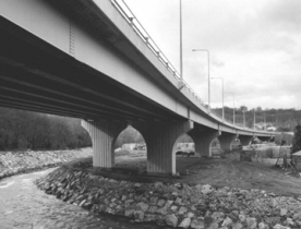
Highfield bridge, (image courtesy of Rotherham MBC)
[top]Design of curved highway bridges
Generally, with the analytical software now available, design analysis of curved configurations is relatively straightforward. However, when steel girders are curved in plan, torsional effects are introduced (the ‘radial’ force mentioned above are in opposite directions top and bottom) and these effects must be considered when designing the beams. In the final stage, when the bridge is composite, the torsion effects result in a different distribution of vertical bending between the girders and in bending of the bottom flange between bracing positions. Guidance on the design of curved highway bridges is given in SCI P393.
[top]Bridge articulation
The articulation of curved bridge decks needs to be considered carefully to avoid problems with unwanted transverse displacements whilst minimizing transverse forces due to restraint. Guidance on the options available is given in SCI P393 and in Guidance Note 1.04.


[top]Erection of curved girders

Curved girders can cause complications during erection because the centre of gravity of a girder section will not be directly over the web. Lifting points will have to be chosen such that the girder does not twist as a whole when lifted. Nevertheless, the free ends will twist slightly and this will have to be addressed when connecting to previously erected steelwork. Paired girders are much more stable than single girders, though the curvature does increase the width of the load when transported as a pair. When girders must be erected individually, additional temporary supported may be needed in midspan.
Guidance on bridge erection is given in a separate article and in the BCSA Guide to the erection of steel bridges.
[top]Resources
- Iles, D.C. (2012) Design of composite highway bridges curved in plan. (P393). SCI
- Hendy, C.R.; Iles, D.C. (2015) Steel Bridge Group: Guidance Notes on best practice in steel bridge construction (6th Issue). (P185). SCI
- Guide to the Erection of Steel Bridges, 2005, (Publication no. 38/05), BCSA
[top]See also
- Bridges - initial design
- Modelling and analysis of beam bridges
- Bracing systems
- Connections in bridges
- Bridge articulation and bearing specification
- Design for steel bridge construction