


Service integration
The need for services in all types of buildings has greatly increased, as a consequence of new approaches to working and living, and also to incorporate low or zero carbon technologies New regulations and demands, such as for more efficient methods of cooling, local temperature control, effective ventilation, more efficient methods of heat recovery, combined heat , power and cooling systems, information technology and communication systems and new forms of renewable energy technologies, have also focused attention on how to locate and distribute these services effectively within buildings and to facilitate future maintenance and adaptability.
Steel frames offer many solutions to integrate building services within the structural floor zone including systems such as shallow floor construction and long-span beams with regular or tailor-made openings in the beam webs. This article describes building servicing requirements and explains how to effectively integrate services into steel-framed buildings.


[top]Introduction

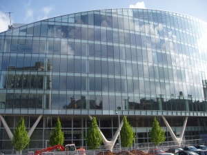
(Image courtesy of FABSEC Ltd.)
Modern buildings require many different types of services for the comfort, health and safety and rapid movement of the users. Building services can be grouped under the following categories:
- Air-conditioning equipment and vertical distribution of air to floors
- Heating and cooling, including local control for each part of the floor
- Fire protection systems, including active measures, such as sprinklers and automatic detection
- Electrical and data communication systems
- Water and sanitary distributions and facilities
- Lifts, escalators and other machinery for vertical movement
- Low or zero carbon technologies for on-site energy generation.
The integration of services within the structural elements of buildings leads to economies in the construction by reducing the floor-to-floor height, which has a double benefit of reducing the external cladding required and also reducing heat loss through the envelope. In multi-storey buildings, service integration can allow extra floors to be provided within the same overall building height.
Steel and composite structures can be designed to reduce the overall depth of the floor zone by integrating major services within the depth of the structure, and/or by achieving the minimum structure depth. This is important in cases in which the building height is restricted for planning reasons, or in renovation projects. For example, a 300mm reduction in floor-floor depth can lead to equivalent savings of £15 to 20/m² when expressed per unit floor area.
[top]Principles of structure-service integration
The basic decision to either integrate the services within the structural depth or to suspend the services below the structure affects the choice of structure, the fire protection system, the cladding details and the overall building height. There are two general approaches to design to accommodate the horizontal distribution of services:
- Minimise the structural zone so that services pass underneath. This is the approach used in shallow floor construction in which the structural zone is only around 300mm.
- Distribute services within the structural zone, for example by provision of large openings within the depth of the steel beams. This is best achieved in long span construction where the beam depth is dictated by structural requirements and large openings can be provided within this depth.
Service routes have to extend both vertically between floors and horizontally to serve the floors. Open spaces, as well as partitioned offices, follow the same basic philosophy in service distribution. The distribution of services emanates from a vertical riser generally at a core, and so the location of the cores and the structural arrangement local to the core is very important to the effective distribution of services. In some systems, local temperature control is provided by a terminal unit which can be located between the steel beams. In others, these local controls are located in the core for ease of maintenance and the ducts to the various parts of the floor are distributed through multiple circular openings in the long-span beams.
The most efficient layout is for the core to be located centrally on plan and for it to house the room air cooling/heating distribution control, electric switching boards, etc, toilets and staircases, lifts, vertical service routes (risers) and safety equipment.
The provision for these routes and systems should be organised with the objective of minimising the space of services and keeping access to services as simple as possible. Prevention of passage of smoke through service route between floors is also important.
[top]Forms of structure-service integration
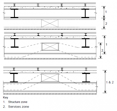

In traditional construction, the services are located in a horizontal layer or zone that is below the floor structure. Therefore there are two separate zones between the ceiling and the floor; a 'structure' zone and 'services' zone. This is called complete 'separation' of services and structure. Systems achieving complete separation of services are usually characterized by relatively short spans and shallow construction depths. For example, the 'shallow floor' or 'integrated beam' systems have been specifically developed to create a flat floor, and to provide flexibility in horizontal service distribution.
When the floor slab is supported by beams of moderate depth, some services can be positioned between the beams, but ducts and pipes still have to pass beneath the beams. This arrangement is called 'partial integration' of services. If the beams are deep enough, it is possible to pass the services through the beams at pre-determined locations so that the structure and services occupy the same horizontal zone. This is called 'full integration' of services. These forms of structure/service integration are illustrated in the figure.
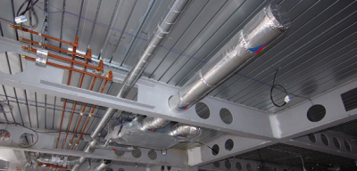
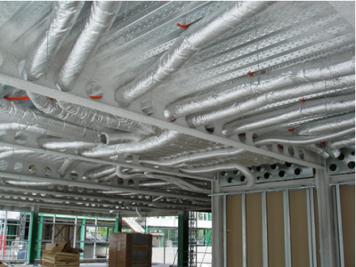
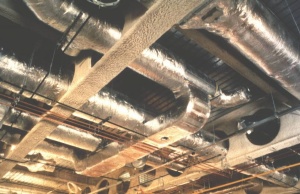
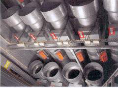
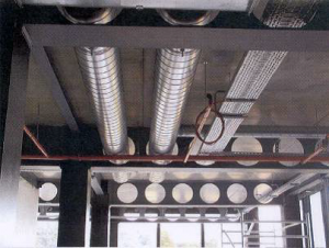
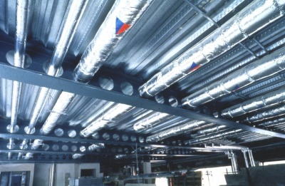
Long-span beams with facility for service integration, can be designed to achieve a ceiling-floor depth less than that of traditional construction in which services pass beneath. Often, careful layout of the structural elements can lead to flexibility in service distribution and ease of future maintenance. The figure below shows the congested distribution of insulated ducting and duct cross-overs that are possible in a long span steel construction, in this case using cellular beams with regular circular openings.

[top]Factors influencing services requirements
The air-conditioning and mechanical ventilation systems can occupy considerable space, and represents a significant proportion of the total building cost. Hence, these requirements should be considered at the initial stages of the concept design of a building, including the decision as to whether an air-conditioning system is needed or not. Many factors influence the sizing and selection of the services systems; these include:
[top]Building location
Location issues that influence the services requirements of buildings include:
- Climate - Variations in solar radiation, air temperature and humidity all affect the energy requirements of a building
- Exposure and orientation - The height of the building and the direction of prevailing winds will also affect the energy usage in a building. Solar gain will occur on south facing façade which influences the strategy for shading and cooling.
- Pollution - This is a consideration in an urban environment, due to noise and traffic fumes. If the building is effectively 'sealed' on its sides subject to these effects the mechanical ventilation systems are required to deliver fresh air for ventilation.
- Shape of site - The shape of the site may dictate the form of the building, which affects both system selection and energy usage.
- Surrounding buildings - Other buildings may reduce daylight penetration and solar gains, and possibly wind patterns around the building may affect the ventilation conditions.
- Planning Considerations - National and local regulations, may influence the building services used. For example, most authorities now require a proportion (10 or 20%) of on-site renewable energy provision, which affect the building services requirements.
[top]Building use
The use of the building, or even parts of the building, dictates the desired internal temperatures, the required degree of control and the operational period of the building, e.g. 8am to 7pm, or in the case of some buildings, 24 hours over which the working conditions must be maintained. Capital and running costs should also be taken into consideration in the selection of the building services.
[top]Building form and construction
The form of the building itself also affects the service needs and type of system chosen.
[top]Building shape
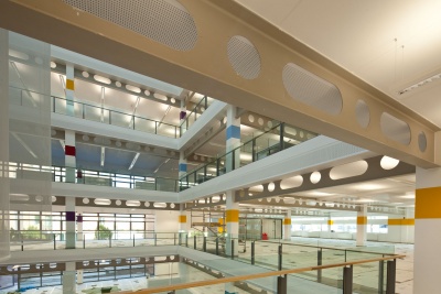
Ideally, the ratio of the envelope surface area to usable floor area should be minimized. However, relatively narrow buildings may in fact use less energy than deep plan structures because they may not need air-conditioning and do not need as much artificial lighting. Benefits of natural light and ventilation from windows can extend up to 6m inwards from the building façade. Many large buildings incorporate an atrium in order to increase the amount of lighting to the inner parts of the building.
Many modern office buildings have a floor depth of 15 to 18m without internal columns, which requires that effective ventilation and lighting have to be provided to the inner part of the building space. However, it is possible to locate conference rooms and storage facilities more towards the inner part of the building to increase the amount of space that can be used for open plan office space closer to the perimeter of the building.
For tall buildings, the most efficient plan shape is a square in which the core is located centrally on plan. This means that the depth of the building for effective ventilation and lighting is reduced relative to that of a building of rectangular plan.
[top]Building mass

All major elements of a building; that is the floors, external walls and roof contribute to the building's thermal capacity or thermal mass. The effect of the 'thermal capacity' of the building fabric can be important over a daily temperature cycle if the structure is able to absorb heat during the day therefore to retard the temperature rise of the enclosed space, and then discharge the heat that is built up over night. This effect is less important in the temperature cycle is of a longer duration say 3 or more days, or if the building is air-conditioned so that its internal temperatures are more uniform. It is useful in an office building which is not occupied in the evening and where the high temperature in the floor slab can be 'purged' at night by passing colder air over it to remove its excess heat .
In a lightweight building, with large amounts of glass and/or lightweight insulated cladding panels in the external envelope, speed of response is therefore important in the design of the services system if a constant internal temperature is to be maintained.
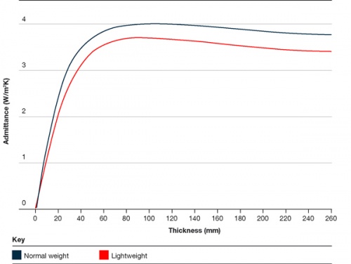
Admittance is the term used to measure the ability of a material to exchange heat with its surroundings. Admittance is limited by the rate of heat transfer between the material and its environment.
Lightweight building materials, such as dry lined partitions, have a low admittance, or a low ability to store and release useful amounts of energy. By contrast, exposed structural elements such as floor slabs have a high admittance. The variation of admittance with thickness of a concrete upper floor slab is shown.
Studies have shown that, on a daily 24 hour cycle, the maximum value of admittance for a slab exposed from underneath only may be achieved with only 75-100mm of concrete. This means that, where heating and cooling takes place over a daily cycle, a floor thickness of 100mm will provide the maximum amount of fabric energy storage possible. If more mass is provided, it will not be utilised.
A ribbed composite floor slab actually performs better than solid slab as the exposed perimeter of the decking permits greater transfer of heat in a given time step, and the effective slab depth exceeds the minimum depths noted above for heat storage over a daily temperature cycle.
[top]Building orientation
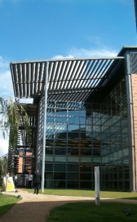
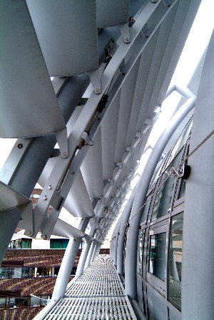
Solar gain occurs through South-facing windows which can advantageous when the ambient temperature is relatively cool. However, it also contributes to over-heating in the summer. Therefore some form of horizontal solar shading should be considered. The shading should be positioned so that the sun at higher angle to the horizontal is shaded, but at a lower angle is not. On the East and West facing walls, vertical solar shading may be considered.
In air-conditioned buildings, the major axis of the building should ideally be in the East-West direction for optimum performance, as it leads to a lower cooling load, which becomes more significant as the amount of glass used in the building envelope increases.
- Steel solar shading systems


[top]Thermal insulation levels
The walls and roof of a building should have an appropriate level of thermal insulation to reduce heat loss. However, modern offices often consist of a high amount of glass which for the North facing walls is generally triple glazed. The U-value of triple glazing is around 0.8 W/m², which although significantly lower than for double glazing, is still much higher than a highly insulated façade wall, where a U-value of 0.2 W/m² can be achieved easily.
Heat loss through the roof can be a major factor for low rise buildings of large plan, but this is less important for multi-storey office buildings.
[top]Glazing

The amount of glazing provided in the external envelope is the most influential factor on the sizing of the heating and cooling systems. A simple rule often used is that 20-30% glazing of the façade provides the benefit of natural lighting and ventilation to a depth of about 6 m from the windows. If a greater amount of glazing is used, more solar protection may be necessary to prevent excessive heat gains and to reduce cooling loads. The choice between openable or sealed windows is dependent upon a number of factors; such as building use, external noise and air pollution levels, site wind speeds, building height, security, etc. Furthermore, the possibility to open a nearby window also gives great psychological benefit to the building users.
[top]Lighting
The level of lighting required for the space is dependent upon the task being performed. Recommended task lighting levels are given in national Codes and are dependent on the building shape, location and the percentage of glazing in the external façade. Deep plan buildings have a greater requirement for artificial lighting.
In highly energy efficient buildings, lighting can be one of the major sources of electricity use and hence associated carbon emissions. Lighting is increasingly in the form of motion detection systems that save on energy use.
[top]Ventilation and cooling systems
[top]Ventilation
In a building where natural ventilation through opening windows in the external walls is not possible, or where the internal environment necessitates particular ventilation conditions, fresh air will have to be provided to the space via mechanical ventilation. Fresh air supply is normally expressed in terms of the 'air change rate', or air changes per hour (ach). Typical recommended air change rates range from 6 in offices, to 10 - 15 in restaurants and other special applications. Alternatively, the air supply may be expressed in terms of the air required by each occupant. For high quality applications, an air supply rate of 8-10 litres/sec/person is required to maintain a fresh atmosphere.
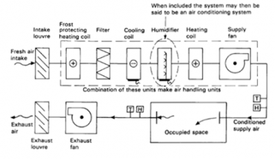
The various components of an air-conditioning or comfort cooling system are shown diagrammatically in the figure. In all cases, cooling is provided by refrigeration, and the low grade heat extracted from the building exchanges its heat with the incoming air to improve the thermal efficiency of the system. The mechanical equipment for delivery of fresh air and refrigeration is generally located on the roof of the building, but local temperature control is provided by the terminal units above the space.

The internal 'set temperature' of typically 20 to 23°C determines when the cooling system is active, and clearly the higher the set temperature, the less energy that is required for cooling. Heat gains from communication and electronic equipment can mean that cooling is required for much of the year in many commercial buildings. The cooling system is obviously required to perform at a higher intensity in summer to cool the internal space and the peak cooling demand can be as high as 70 W/m² floor area.
[top]Mechanical ventilation
The air change rate has to be enhanced mechanically in areas which cannot be naturally ventilated by opening windows in the external wall. When both the cooling coil and humidifier are removed from the air-conditioning system in the figure, the remaining system is known simply as a 'mechanical ventilation' system. The air is heated in winter, but in summer, air is supplied at the prevailing external temperature, which is often in excess of the desired internal space temperature. The internal temperatures in the summer are therefore dependent upon the outside temperature, which may be unacceptable to the occupants, or to the specialist processes inside the building. In this case, some form of cooling is incorporated into the mechanical ventilation system.
[top]Comfort criteria
The cooling effect on the occupants within a building is influenced by three factors:
- Ambient air temperature
- Surface temperature (radiation)
- Air movement (convection).
These three effects influence the design of the ventilation and cooling system. Detailed research of occupant comfort in buildings has led to the establishment of an empirical comfort factor called the 'resultant temperature', which is defined as:
Resultant temperature = 1/2 x Air temperature + 1/2 x Room surface temperature.
Air speed is usually low in modern commercial buildings and its effect on the resultant temperature can be neglected. The total cooling effect is therefore a combination of supplying cool air, and/or cooling of the surfaces of the space thereby affecting radiant cooling.
[top]Types of air-conditioning system
There are three main components to an air-conditioning system; the central heating/cooing machinery, the distribution/control system and the terminal outlet devices. The generic types of air-conditioning or 'comfort cooling' systems are:
- All air systems: Constant Volume, or Variable Air Volume (VAV)
- Air-water systems: Fan Coil Units (FCU) and active chilled ceilings or chilled beams with a primary air supply.
- All water systems: Unitary Fan Coil Units and reversible heat pumps, Fan Coil Units without primary air supply.
- Refrigerant Split and packaged refrigerant systems: systems, with or without primary systems air supply.
The most commonly used 'comfort cooling systems' for office building applications are VAV and FCU systems, but increasingly, active chilled beams are used.
Often, VAV systems are used in buildings with single owner occupiers, because of their lower running costs. Fan Coil systems are more often used in speculative buildings because of the lower capital costs and greater degree of local control to the space being serviced. Chilled beams are increasingly used where air is delivered centrally and cooled through the linear elements known as chilled beams, and this system can operate effectively in heating and cooling.
Often these systems are used in conjunction with perimeter heating, which is sometimes located in the raised floor, where it is known as 'trench ' heating. The perimeter heating offsets the local heat losses through highly glazed façades.
More information on these generic systems, their advantages and disadvantages, is given in SCI P166 .
[top]Under-floor distribution
Air-conditioning system distribution and terminal equipment is generally located overhead in the ceiling void with the cool supply air entering the room from ceiling diffusers. However, the supply of conditioned air from under the floor is a design option. In this case, the air or water distribution and terminal devices are located in the floor void, and hence the overhead services are reduced to only lighting and sprinklers. The two solutions of under-floor and over-head service distribution are illustrated below.

|
|
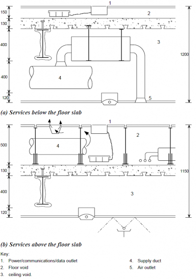

By making the floor void deep enough, the power, telecommunications and computer wire-ways may be incorporated into the one plenum, all being easily accessible by merely opening up the raised floor. Under-floor cooling is particularly beneficial for spaces such computer rooms, as air velocities from floor grilles and resultant noise levels are both much higher for cooling of equipment than those which would be acceptable for people.
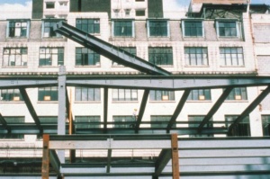
Under-floor systems can be beneficial when the floor slab is exposed, when it is used as part of the thermal capacity of the building fabric. A good example of this design approach is shown below in which the curved precast concrete floors are supported on deep asymmetric steel beams which project above the concrete slabs to form the floor plenum.
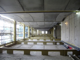

(Image courtesy Buro Happold)
[top]Internal distribution of services
For many reasons, there is pressure to minimise the space allocated to the building services. Therefore, it is necessary to ensure an efficient use of space for the service distribution system in the vertical and horizontal directions and in the plant rooms. The following sections review the spatial aspects of the vertical and horizontal service distribution.
[top]Vertical distribution of services

The following recommendations apply to the vertical distribution of services:
- Provide continuous and uninterrupted vertical service routes
- Maintain a constant cross-section of the service route
- Position the plant room so that it is as close as possible to the centre of the plan area it serves
- Consider the connection between horizontal services and vertical services routes
- Provide separate routes for different services. The minimum is two; one for electrics and one for water pipes, etc., although most buildings require more service routes
- Horizontal distribution should ideally not extend more than 25 m from a vertical service route. Longer distances will impose penalties on the system design and increase the depth of horizontal service ducts
- Position plant rooms at no more than 10 storeys apart vertically.
The figure below shows typical arrangements of vertical service routes. Vertical ducts which transfer air from the roof-top plant to each floor can often be concentrated in a relatively small riser, as shown below.
| Type | Plant | Notes |
|---|---|---|
| Small building (up to four storeys and up to 2500 m2 total floor area) | 
|
One plant room, one riser. Location of riser not important, due to small size of building (central location preferred). Plant room must be adjacent to the riser |
| Large plan building (4000 m2 total floor area) | 
|
Several plant rooms adjacent to areas served. Some central plant, for example for gas intake and boilers, may be required |
| Large, tall building (over 15 storeys) | 
|
Plant room floors at basement and roof level. Intermediate plant rooms may be required. Vertical distribution within central core |
| L-shaped building (1000 m2 to 3000 m2 per floor), (3 -10 storeys) | 
|
Several plant rooms, several risers. Risers and air plant rooms adjacent to cores. Separate room located at ground/basement level for new electric supply |
| Building with atrium (typically 2000 m2 per floor), (5 – 10 storeys) | 
|
Four roof air plant rooms, one basement plant room. Four risers related to cores. Basement plant below atrium gives best connection to risers |
[top]Horizontal distribution of services
Conventionally, the horizontal distribution of services is arranged within a horizontal layer which is generally located below the structure and above the suspended ceiling. This layer accommodates the distribution system (ducts, pipes, etc), the terminal units and lighting units. The raised floor is placed on the floor slab and accommodates the electrical and communication cabling. The lighting units are often located within the ceiling depth.
To determine the spatial allowance for these elements, three design cases may be envisaged corresponding to different structural configurations:
- A flat slab with flexibility of service routing.
- A slab and downstand beam arrangement.
- A long span beam system with facility for service integration in the structural depth.
In case 1, the ducts pass below the floor within the depth allowed for the terminal units. However, cross-overs of ducts must be avoided in order to minimize this depth. In cases 2 and 3, the terminal units may be located between the beams, which means that additional space below the beams is required only for the major ducts, ceiling and lighting units. In case 3, the ducts are located entirely within the structural zone as they pass through large openings in the deep beams. Typically, the diameter of these openings is 400mm, and the duct size is 300 or 350mm allowing for insulation etc.

|
|
|
|
|

|
|

|
|
Typical dimensional allowances for service zones in typical modern air-conditioned buildings are shown in the table for these three cases. It can be seen that ceiling-floor depths of 1,100 to 1,200 mm are commonly required. The difference between the overall ceiling-floor depths for the case of flat soffit and the long-span systems with integrated services is relatively small. Also, in modern long span construction, intumescent coatings are used for fire protection and so the allowance for the thickness of fire protection can be neglected. A raised floor of 150 or 200mm depth is required in all systems.
| Vertical dimensions for the following components | Case 1 Flat soffit (mm) |
Case 2 Downstand beams (mm) |
Case 3 Long span beams (mm) |
|---|---|---|---|
| Allowance - deflection & fire protection | 30 | 50 | 50 to 75 |
| Lighting units and ceiling | 100 to 150 | 100 | 100 |
| VAV box and attachments | 400 | Nil | Nil |
| (boxes between beams) | |||
| Ducts and insulation | <400 , but no cross-overs |
400 (inc. insulation) | Nil- 400mm dia. openings |
| Total (below structure) | 550 | 500 | 150 to 175 |
| Raised floor | 150 | 150 | 150 |
| Structural depth (typical) | 300 to 400 | 550 | 800 to 900 |
| Total (ceiling-floor) | 1,000 to 1,100 | 1,200 | 1,100 to 1,200 |
It is possible to reduce these ceiling-floor depths, but the cost of the structure, and services (due to inefficient duct shapes, or number of separate ducts) may increase.

[top]Steel framing options
This section describes the main structural steel systems and their characteristics in relation to their compatibility with services. All the structural systems described utilise composite floor slabs.
[top]Composite construction


In composite construction , steel beams act structurally with an in-situ and lightly reinforced concrete slab on steel decking, known as a composite floor. A composite beam may be twice the strength of the equivalent non-composite beam in conventional steelwork, and up to four times stiffer. This means that shallower structural depths can be achieved which permits use of lower storey heights and leads to savings in cladding costs, or alternatively, provides more space or flexibility for placing of services within the same overall floor-to-floor height.
[top]Shallow floors
Shallow floors achieve the minimum structural depth and therefore provide maximum flexibility for distribution of services beneath the floor. A number of shallow floor solutions are available including Ultra Shallow Floor Beams (USFB) from Kloeckner Westok, and ArcelorMittal's Slim floor beams. The common theme is that the beams are asymmetric with a wider bottom flange than top flange. three alternative floor systems may be used with these integrated floor beams: precast concrete (pc) units, deep deck composite slab and shallow deck composite slab, all of which are supported on the wider bottom flange.

(Image courtesy of Kloeckner Westok)
[top]Medium span systems
The structural grids used in modern offices are generally based on multiples of 1.5m, and therefore spans of 7.5, 9, 12, 13.5, 15m and up to 18m are often specified. In the orthogonal direction, spans of 6, 7.5 and 9m are used in order to conform to the span capabilities of the cladding system and so the floor grid is rectangular on plan. The composite slab spans typically 3 to 4.5 m between the beams and is 130 to 150mm deep. Secondary beams are used to support the slab and these beams span between primary beams.
The most efficient layout of the floor beams is where the secondary beams span the longer distance and the more heavily loaded primary beams span the shorter distance in the floor grid. For medium spans, which are defined as in the range of 7.5 to 12m, hot rolled steel I beams of 350 to 530mm depth are generally used and are designed to act compositely with the floor slab.
In medium span systems, the depths of the primary and secondary beams are selected so that the services distribution systems pass beneath. The terminal units in the services system are located between the beams, and so are within the structural depth.
[top]Long span construction
Building users and developers are frequently demand more column-free space, and 12 to 18 m column spacings have become more popular. Agents find that column-free spaces easier to let and command a rent premium. A variety of structural solutions for long spans, (i.e. above 12 m) will be considered. In a typical framing plan, the secondary beams span the longer distance and the primary beams span 6 to 9m depending on the cladding system. The span:depth ratio of long span secondary beams when designed compositely is typically 20 to 22, which means that the beam depth for a15m span can be 700 to 750mm. It is possible to design a service zone of 400 to 450mm within the structural depth.
Cellular beams , fabricated tapered girders, haunched beams, parallel beam systems, composite trusses, stub girders and other long span systems have been developed and may be used depending on the floor grid. The optimum structural solution depends on the:
- Spans of the primary and secondary beams. Fabricated members are often more efficient for heavily loaded primary beams
- Span/depth ratio of the members
- Necessity to contribute to the resistance to lateral loads applied to the building
- Location and cross-sectional area of major ducts across the span (including consideration of general distribution routes and crossover positions)
- 'Looseness of fit' between services and structure, (especially important for 'shell and core' developments, where particular tenants may require additional provisions)
- Structure cost taking account of savings in cladding and other costs
- Access and maintenance costs
- Future requirements for re-servicing.
Guidance is given in SCI P166.
[top]Composite beams with web openings

Reserve capacity exists over much of the length of a rolled steel section and this permits rectangular or circular openings to be cut in the web, provided these openings are located away from the supports. Relatively large openings can usually be provided without the need for strengthening by horizontal stiffeners, provided that there is adequate shear resistance in the remaining web. The high degree of composite action around the openings means that the loss of bending resistance of the beam due to the web openings is often not as significant as in a steel beam.
Circular openings are more efficient structurally than rectangular openings. If larger service zones are necessary, more costly 'stiffened' rectangular openings are required. Opening sizes and positions can be 'tailored' to meet the specific requirements of a particular service distribution strategy.
When locating rectangular openings in the webs of composite beams, the following guidelines should be considered in order to minimize the effect of the openings on the beam design:
- Openings should not be located closer than two times the beam depth (D) from the support, or 10% of the span, whichever is the greater
- The best location for any opening is between 20% and 35% of the span from the supports in uniformly loaded beams
- For beams subject to point loads, the location of the openings depends on the relative importance of moment and shear along the beam
- Openings should not be less than the beam depth, D, apart unless checks are made on the web-post between the openings
- Unstiffened openings should not generally be deeper than 0.6 D, nor longer than 1.5 D. The shear resistance and instability of the web should be checked
- Stiffened openings should not generally be deeper than 0.7 D, nor longer than 2 D. Stiffeners should be in the form of horizontal plates welded above and below the opening
- Point loads should not be applied at less than D from the side of the adjacent opening.
As an alternative near supports, beams may be notched by cutting away the lower part of the beam web and flange. As much as half of the beam depth, D, can be removed extending up to distance D into the span. This permits the use of modest service zones adjacent to the supports of long span beams.
[top]Cellular beams

Lighter deeper sections can be fabricated from structural sections in the form of 'cellular' beams. These sections are produced by cutting hot rolled steel sections and re-welding them to create deeper beams with a series of circular holes. The sections are structurally efficient, and relatively large openings can be created through which services can be passed.
Cellular beams are more suitable for use as long span secondary beams than for primary beams, as the shear capacity of the web is considerably weakened by the openings. However, they can be designed for use as primary members by strengthening the openings where shear forces are very high, either by infilling the openings or by using horizontal stiffeners.
An alternative form of cellular beams uses fabricated sections in which the flanges sizes and web thickness and depth can be selected to be most efficient for the applied loading and opening sizes. Fabricated cellular beams are more efficient for heavily loaded primary beams as the web thickness can be increased relatively easily.
For 'cellular' beams, a wide range of opening sizes and beam sizes is possible. The opening diameter is typically 0.6 to 0.8 times the final beam depth and the centre-centre spacing is typically 1.5 times the opening diameter. Furthermore, where shear forces are low, the openings may be elongated by removing the 'web post' separating two adjacent openings.
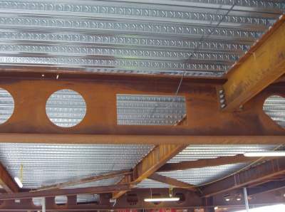
For composite beam design, the top Tee or flange may be significantly reduced in size relative to the bottom Tee or flange . A combination of different UB and UC sections can reduce the weight of a beam by up to 30%, whilst providing the same composite stiffness as a solid beam of the same depth. The production process for cellular beams also allows the sections to be pre-cambered during production, effectively overcoming deflection problems due to self weight. The ability of cellular beam to accommodate a large number of circular ducts is illustrated in the figures in this section.
Cellular beams are used where a high degree of flexibility in service routing is required and this form of construction has become the most common way of designing for long spans of 13 to 18m typically.

(Image courtesy of Kloeckner Westok)
[top]Haunched beams
Haunches, or local deepening of beams adjacent to the beam to column connection, can also be used to reduce beam depths for long spans. Large moments are transferred into the columns, resulting in more expensive connections and heavier columns, but the beam depth is significantly reduced. Haunched beams can also be designed to provide the sway stability of the building without requiring vertical bracing. Therefore, they tend to be used in medium-rise buildings (up to 6 storeys high), where bracing can be eliminated in at least one direction.
Therefore, span/beam depth ratios can be increased to around 35, corresponding to about 30% reduction in beam depth relative to simply supported composite beams. The critical section for design is the beam at the tip of the haunch. The length of the haunch is selected to achieve an efficient moment connection to the column. A haunch cut from the same section (of depth D) is usually used, resulting in an overall depth at the supports of approximately 2 D. Consequently, a clear zone of depth D (typically 400 to 500 mm) is provided across approximately 85% of the beam span. A shallow beam depth therefore permits the services to be passed beneath the beams within the depth of the haunches. This gives greater freedom in design of the service layout and easier installation on site.
Despite these advantages, the haunched beam solution requires careful structural design because the beams must frame into the major axis of columns in order to transfer moments to the required columns. The haunched beam system is ideally suited to buildings with rectangular plan form and is not generally appropriate for irregular building plan shapes.
[top]Tapered beams

As an alternative to rolled sections, fabricated steel sections produced from flat plate can be used. Additional fabrication costs can be offset against reduced material costs, resulting in a structurally efficient and economic design. Fabricated sections may be of uniform depth, but tapered beams offer advantages in highly serviced buildings. By tapering the beam along its length, the bending resistance of the section can be made to closely follow the shape of the bending moment diagram. At the ends of the beam, the depth may be reduced, depending on the required shear resistance. This saves weight of steel, but more importantly, provides space below the beams for service distribution. Thus a reasonably sized zone is created in which services may be accommodated adjacent to the columns. Service distribution in the other direction can usually be provided in the zone beneath the secondary beams.
Beams with a straight taper to mid-span are simpler to fabricate and are the most economic shape- see the example below. Typical tapered girders reduce to approximately half depth at the supports with a maximum taper angle of about 6°. A vertical stiffener may be required at mid-span for deeper sections. A practical range of span/depth ratios is from 15 to 20 and a 400mm deep x 1000mm wide service zone can be provided next to the columns in a beam span of 15m.
[top]Composite trusses
Composite trusses may be designed for long span applications of 15 to 20m, and comprise either angles and Tee sections or for more heavily loaded applications, Square Hollow Sections . The bracing members are located in a W-form so that sufficient space is provided for large ducts.
Composite trusses are relatively expensive to fabricate but potentially lightweight. The connections to the columns are generally made through the top chord of the truss and the bottom chord does not extend to the column which provides a local service zone to the columns. Allowance must be made for the thickness of fire protection around the relatively slender chord and bracing members.
[top]Stub girders
Stub girders were sometimes used to provide long spans in two directions for 'dealing room' floors etc. In this system, the bottom chord is a UC section and in the orthogonal direction, UB sections run continuously over the bottom chord. Short sections of beams are welded to the bottom chord to provide the longitudinal shear transfer to the composite slab that forms the top chord to the composite system.
The two way spanning system can span up to 20m but it has the disadvantage that the bottom chord has to be propped until the concrete slab has gained adequate strength. Often a tee section is embedded in the slab and acts as the top chord of the stub girder.
Stub girders have not been widely used since the 1990s but are an economic solution where a high degree of service integration is required in long span systems.
[top]Parallel beam systems
Parallel beam systems comprise pairs of continuous primary beams, generally spaced apart by the column sections which support the floor. In the orthogonal direction, continuous beams (generally composite) are supported by the pairs of primary beams. Because the primary beams are continuous, and arranged in pairs, shallow sections may be utilised. A high degree of service integration is provided in both directions.
[top]Summary of service zones provided by various structural systems
Each of the structural options presented above can accommodate openings for services but to varying degrees. Some systems are particularly well adapted to the provision of a large number of small openings, whereas others provide a small number of larger openings in certain prescribed locations. In the selection of a particular structural system, it is therefore necessary to consider the requirements of the services system. As a broad guide, the table below presents typical opening sizes for the range of structural systems. The table is based on efficient structural design of the beams. Larger openings may be possible, if the structure is over-designed.
| Structural option | Span/depth of primary beam¹ | Opening size for beam span of: | |
|---|---|---|---|
| 12m | 15m | ||
| Composite beam with stiffened openings in low shear regions | 25 | 2 @ 300 x 600 | 1 @ 400 x 1000 + 2@ 350 x 700 |
| 20 | 2 @ 400 x 800 | 1 @ 500 x 1200 + 2@ 450 x 900 | |
| Composite beam with stiffened openings in high shear regions | 25 | 2 @ 250 x 450 | 4 @ 300 x 600 |
| 20 | 2 @ 300 x 500 | 4 @ 375 x 750 | |
| Composite beam with notches at ends of beams | 25 | 2 @ 250 x 450 | 2 @ 300 x 600 |
| 20 | 2 @ 300 x 600 | 2 @ 375 x 600 | |
| Castellated beam² | 20 | 20 @ 240 diameter | 20 @ 300 diameter |
| Cellular beam | 20 | 20 @ 350 diameter | 22 @ 400 diameter |
| Haunched beam | 30 | 250 x 9000 | 300 x 12000 |
| Tapered beam | 20 | 2 @ 200 to 400 x 3000 | 2 @ 250 to 500 x 3000 |
| Composite truss | 17 for 12m span 20 for 15 m span |
4 @ 400 diameter + 6 @ 250 diameter |
4 @ 400 diameter + 6 @ 250 diameter + 1 @ 450 x 1000 |
| Stub girder | 20 | 4 @ 300 x 900 + 4 @ 300 x 600 |
2 @ 400 x 1000 + 4 @ 400 x 700 + 4 @ 400 x 500 |
| Parallel beam system | 30 - secondary 15 - primary |
400 deep continuous | 400 deep³ continuous |
Assumptions:
- Ceiling - floor zone = 1250mm
- Structural zone (beams and slab) = 900mm
- Beam spacing = 6m
- ¹ Depth of steel section depth. Slab depth (about 130mm) to be added
- ² May be restricted to applications as long span secondary beams
- ³ Structural zone deeper than 900mm
[top]Further reading
- British Council for Offices Guide to Specification, BCO, 2014
[top]Resources
- SCI P166 Interfaces: Design of Steel Framed Buildings for Service Integration, 1997
- IEP2 Service Co-ordination with Structural beams . Guidance for a Defect-free Interface, BSRIA, SCI, 2003
- IEP4 Supporting Services from Structure. Guidance for a Defect-free Interface, BSRIA, SCI, 2004