


Shear connection in composite bridge beams
Shear connectors on the top flanges of the steel girders provide the means to achieve composite action between the slab and the girders, thus increasing both stiffness and strength. This article reviews the behaviour of the connectors and the design rules for the shear connection in BS EN 1994-2[1]. Further guidance is given in Section 6.5 of SCI P356 and examples of the calculation of shear resistance are given in SCI P357.
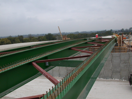

A41 Aston Clinton Bypass
[top]The need for shear connection
The shear flow between steel beam and reinforced concrete deck slab is a natural consequence of the requirement for composite action. If there were no connection, a beam and slab would bend as illustrated diagrammatically below. The presence of a shear connection prevents the slip between the two components and achieves a much stiffer and stronger beam.
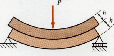

When there is shear connection, the two components behave as one.
[top]Longitudinal shear flow, elastic design
According to elastic theory of bending, the stresses and strains in a beam in bending vary linearly from the extreme tension fibre to the extreme compression fibre and the shear flow at any level (relative to the neutral axis) in the cross section is given by:

For both A and I, the area of concrete should be taken as its transformed area, i.e. its actual area divided by the modular ratio. When evaluating shear for hogging moment regions, the slab should be considered to be un-cracked. (This is a conservative simplification and is applicable except when tension stiffening and over-strength concrete are explicitly considered, although there is no guidance in BS EN 1994-2[1] for evaluation in those situations.)
In practice, the magnitude of the shear flow varies along the beam and the required resistance could be provided to match that variation exactly but it is much easier to provide a uniform resistance over the whole beam, or more economically, over a few lengths of uniform provision.
For the latter option, in each length of uniform resistance, the resistance could be made to match the peak value of shear flow over that length but a further simplification is allowed by BS EN 1994-2[1], Clause 6.6.1.2, which permits, in any length of constant resistance, the design shear flow to exceed the resistance per unit length, provided that:
- the peak shear flow within each length does not exceed the design longitudinal shear resistance per unit length by more than 10%
- and the total design longitudinal shear over the length does not exceed the total design resistance for this length.
The shear connection is normally provided by shear stud connectors, in rows. The above rule allows the designer to specify rows generally uniform spacing along the beam: more studs are provided in rows adjacent to supports, where shear is highest. In some cases the spacing of the rows might be increased in midspan regions. In all cases, the spacing of the rows of studs and the spacing of the transverse reinforcement need to be matched, to avoid clashes.
[top]Longitudinal shear flow, plastic design
Where the resistance of beams is based on the plastic resistance of the cross sections, the above expressions for shear flow are not valid as the material behaviour is non-linear and shear flows cannot be calculated from linear elastic analysis. BS EN 1994-2[1] clause 6.6.2.2 (1) covers this case for Class 1 and 2 members.
BS EN 1994-2[1] Clause 6.6.2.2 (2) gives specific cases of a concrete slab in compression. The longitudinal shear flow has to be determined by considering the change in the force in the slab over the length where the bending moment exceeds the elastic resistance. Clause 6.6.2.2 (3) covers slabs in tension and clause 6.6.2.2 (4) allows gives an alternative approach where the elastic section analysis is used based on the uncracked cross section properties. The slightly unconservative neglect of inelasticity in this case is offset by the conservative assumption that the section is uncracked.
[top]Resistance of shear connection
[top]Headed stud shear connectors
As mentioned above, the most common form of provision for shear connection is the headed stud, welded to the top flange. Studs are generally placed in rows, the spacing (and thus the number per unit length) being dependent on the design shear force between girder and slab.
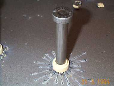
Typical shear stud connector, immediately after welding

Groups of shear connectors


For stud shear connectors, the design resistance of a single stud is the lower of the resistance of the stud itself and of the concrete around the stud. This is expressed in BS EN 1994-2[1] as the design resistance is the lower of:

Limits are given on the spacing of studs - see further discussion below.


Whether the strength of the stud or the strength of the concrete governs depends on the relative strength of the stud and the concrete. The variation of the values given by the two expressions can be expressed graphically - for a 19mm stud the relationships are as shown right.
Note that BS EN 1994-2[1] refers to the strength of stud connectors to BS EN ISO 13918[2]. In that Standard there are two types of carbon steel stud connectors; the strength of the higher grade stud is 450N/mm2 and this will normally the type that is used.
It can thus be seen that for most composite bridges, where the concrete grade is greater than C25/30, the strength of the connection is determined by the stud itself.
Slabs tend to ‘ride up’ the weld collar, so a minimum tensile resistance of 10% of shear resistance is required by BS EN 1994-2[1] – this is deemed to be provided by headed studs. Tensile design forces less than this may be ignored.
For greater tensile design force, no interaction relationship between tension and shear resistance is given but it is suggested in Hendy and Johnson[3] that the following criterion may be used:

The fatigue resistance of shear connectors must also be considered
[top]Other forms of shear connector
BS EN 1994-2[1] does not provide rules for any other type of shear connector, although principles are given for determining the resistance of other types of connection. The intention was not to preclude alternative forms but to stimulate innovation. If alternative forms of shear connector are considered (for example, where a higher shear resistance per connector is needed, such as in some connections at integral abutments), the following guidance is given in BS EN 1994-2[1]:
- All shear connectors should have a resistance to tension of 0.1PRd to prevent separation
- Rules for the strength of the concrete and the steel components in BS EN 1992 and BS EN 1993 may be used to derive resistances.
Hendy and Johnson[3] give a derivation of the resistance of block and hoop connectors, which is a common alternative form of connector. The design of this type of connector is based on the following premise:
- The shear resistance is given by the limiting concrete bearing pressure on the face of the block (see clause 6.7 BS EN 1992-1-1[4] for bearing pressure).
- The hoop is designed to have a resistance against an uplift of at least 0.1PRd.
- The welds are designed in accordance with BS EN 1993-1-8[5] for the resulting shear, tension and bending.
- Fatigue of the welded connection is verified in accordance with BS EN 1993-1-9[6].
[top]Detailing
Rules are given in BS EN 1994-2[1] on the positioning of studs and their height relative to transverse reinforcement.
[top]Resistance to separation
To avoid the creation of potential shear failure planes that pass over the shear connectors and under the transverse reinforcement, the connector spacing and height of bottom reinforcement are limited in BS EN 1994-2[1] clause 6.6.5 . Tests have found that the longitudinal failure surfaces are not always planar. A longitudinal section through a possible failure surface is shown. The dimensions shown are drawn to the limits in BS EN 1994-2[1]. The example shows that α is about 8°. Hendy and Johnson[3] view this as too flat to prevent failure and recommend a minimum value of 17°. This would give a maximum spacing of 450mm with 50mm bottom cover and a 125mm tall shear stud (length after welding being 120mm typically).


[top]Maximum spacing of connectors
The maximum longitudinal spacing of connectors is given by BS EN 1994-2[1] clause 6.6.5.5(3) as 4hc (where hc is the slab thickness) but not more than 800mm.
BS EN 1994-2[1] Clause 6.6.5.5(2) gives additional limits for connector spacing on plate girders where the flange is taken to be Class 1 and 2 but, without connection to the slab, would be Class 3 or 4.
BS EN 1994-2[1] Clause 6.6.5.5(4) gives rules that to allow connectors to be grouped in pockets (useful when full-depth precast units are used), but then states that the following need to be verified:
- Assumption of plane sections remaining plane
- Vertical separation
- Buckling of steel flange
- Bursting force from group of connectors (transverse rebar rules may not be sufficient).
Stud connectors
BS EN 1994-2[1] clause 6.6.5.7 gives minimum dimensions for headed shear studs. The minimum spacing in the direction of the shear force is 5d and the minimum spacing in the direction transverse to the shear force in ‘solid slabs’ is 2.5d. Note that the reference to solid slabs should be taken to excludes slabs with haunches (A minimum spacing of 4d should then be used).
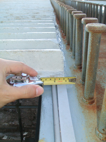
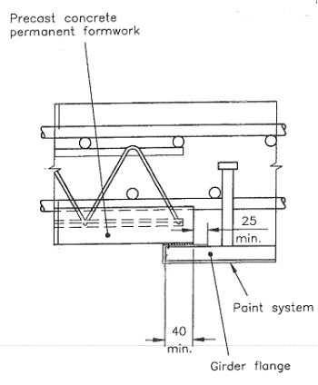
BS EN 1994-2[1] clause 6.6.5.6 gives the edge distance to the shear studs as not less than 25mm. However, where permanent formwork is used, allowance needs to be made for seating the formwork on the girder in accordance with the manufacturer’s requirements. Additionally, protective coating should be returned by at least 25mm from the edge of the flange or, where permanent formwork is used, 25mm from the edge of the formwork (see Soubry[7]). Usually 100mm edge distance is sufficient.
- Paintwork overlap at the edge of the girder adjacent to shear studs


[top]Longitudinal shear resistance of the slab
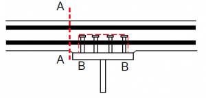

To verify the adequacy of the slab for the forces transferred by the shear connectors, several potential failure surfaces need to be considered. Two shear surfaces are illustrated right.
BS EN 1994-2[1], clause 6.6.6 requires that the longitudinal shear resistance of the slab is verified on shear surfaces of type A-A and B-B; for design shear strength of the concrete flange it refers to BS EN 1992-1-1[4].
BS EN 1994-2[1] clause 6.6.2 defines the design longitudinal shear per unit length VL,Ed between steel and concrete as the rate of change of force in either the steel or concrete element. In the BS EN 1992-1-1[4] truss model for the shear between the slab and beam, requirements are given in relation to the design shear stress VEd. There is some inconsistency between BS EN 1992-1-1[4] and BS EN 1994-2[1] when expressing shear stress but for shear surfaces type A-A it should be considered as the design shear per unit length on one side divided by hf, where hf is the depth of the slab and for shear surfaces type B-B it is the total design shear divided by hf, where hf is the length of the shear plane.
The area of transverse reinforcement Asf at spacing sf that crosses the shear surface is required by BS EN 1992-1-1[4], expression (6.21) to satisfy:
![]()
For surfaces A-A, Asf is the sum of the areas of the top and bottom transverse reinforcement; for surfaces type B-B, it is double the area of the bottom reinforcement.

Additionally, the longitudinal shear stress should satisfy BS EN 1992-1-1[4] expression (6.22) in order to prevent crushing of the compression struts in the flange.

For consideration of the interaction with transverse bending moment:
- On plane A-A, transverse reinforcement to be the greater of that required for longitudinal shear alone and half that required for longitudinal shear plus that required for transverse bending.
- On plane B-B, the area of bottom reinforcement required for transverse bending moment should be fully added to that required for longitudinal shear (although not stated in BS EN 1994-2[1])
For consideration of the interaction with tension:
- If the slab is in transverse tension across A-A (e.g. if the girder is a cross girder in the main beam hogging zone), tension requirements should be fully combined with longitudinal shear.
[top]References
- ↑ 1.00 1.01 1.02 1.03 1.04 1.05 1.06 1.07 1.08 1.09 1.10 1.11 1.12 1.13 1.14 1.15 1.16 1.17 1.18 1.19 1.20 1.21 BS EN 1994-2:2005. Eurocode 4: Design of composite steel and concrete structures. General rules and rules for bridges. BSI
- ↑ BS EN ISO 13918:2018 Welding. Studs and ceramic ferrules for arc stud welding. BSI
- ↑ 3.0 3.1 3.2 Designers’ Guide to BS EN 1994-2 Eurocode 4: Design of composite steel and concrete structures Part 2: General rules and rules for bridges. Hendy, C.R.; Johnson, R.P. (2006). Thomas Telford Ltd
- ↑ 4.0 4.1 4.2 4.3 4.4 4.5 BS EN 1992-1-1:2004+A1:2014. Eurocode 2: Design of concrete structures. General rules and rules for buildings. BSI
- ↑ BS EN 1993-1-8:2005. Eurocode 3: Design of steel structures. Design of joints. BSI
- ↑ BS EN 1993-1-9:2005. Eurocode 3: Design of steel structures. Fatigue. BSI
- ↑ Bridge detailing guide. (C543). Soubry, M. (2001). CIRIA
[top]Resources
- Iles D.C. (2010) Composite highway bridge design (P356 including corrigendum, 2014). SCI
- Iles D.C. (2010) Composite highway bridge design: Worked examples (P357 including corrigendum, 2014). SCI
- Hendy, C.R.; Iles, D.C. (2015) Steel Bridge Group: Guidance Notes on best practice in steel bridge construction (6th Issue). (P185). SCI
[top]See also
- Integral bridges
- Design of beams in composite bridges
- Fatigue design of bridges
- Connections in bridges
- Corrosion protection