


Single storey industrial buildings
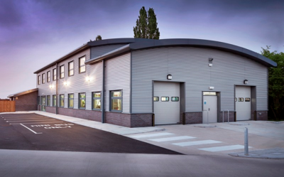
Single storey buildings are the largest sector of the UK structural steelwork market, representing upwards of 60% of total activity. These buildings are typically used for workshops, factories, industrial and distribution warehouses and retail and leisure. Referred to colloquially as ‘sheds’, sizes vary from small workshops of just a few hundred square metres up to massive distribution warehouses covering over one hundred thousand square metres.
Steel dominates the framing systems used in this sector with a market share of approximately 90%. Whilst most single-storey buildings are relatively straightforward building projects, increasing levels of specialisation by steelwork contractors and other supply chain members have, in recent years, led to huge improvements in quality, cost and delivery performance of single storey steel buildings. These improvements have been achieved through increasingly efficient use of the portal frame by design-and-build steelwork contractors, improved project planning, and active supply chain management by main contractors.
This article deals specifically with single storey industrial buildings. Single storey buildings in other sectors are addressed in other articles, e.g. retail and leisure.
- Wasdell Dundalk-2a.jpg


[top]Attributes of steel construction
Main articles: The case for steel, Sustainability, Cost of structural steelwork, Cost planning - Industrial buildings
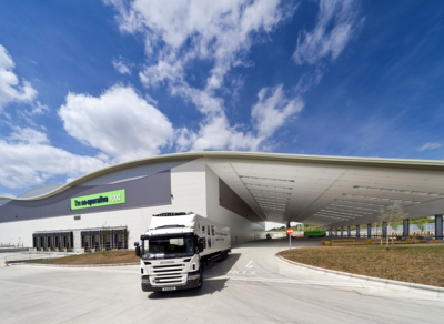

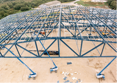
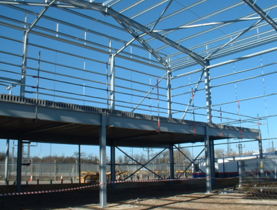
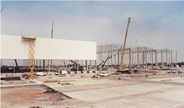
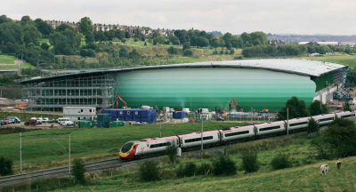
(Image courtesy of Severfield (Design & Build) Ltd)
All clients commissioning buildings have a business case for doing so; they may be building it for their own use, to rent out, as an investment or to sell on. Although industrial buildings are one of the least complicated building forms, there are several criteria which can affect the value that the building brings to the clients and users alike. The attributes of steel construction are routinely used to optimise the business case for single-storey buildings.
[top]Speed of construction

Early return on investment is particularly important for retail and logistics companies and therefore speed of construction is vital. This can affect the design in many ways that are perhaps not immediately apparent. For example:
- The layout and components can be designed so that parallel rather than sequential construction can take place
- Interfaces between trades need to be minimised
- Collaborative discussion between trades will be needed to ensure that, whatever is decided, all aspects of construction can proceed quickly and safely.
Structural steel components are pre-fabricated off-site by a steelwork contractor; any protective coatings that are required can be applied at this stage. Site activity is primarily an assembly operation, bolting steelwork parts together, which leads to short construction programmes. The building can be made weathertight quickly, allowing the following on trades early access to commence their work.
[top]Flexibility and adaptability

Change is now a fact of life for most UK businesses, with the likelihood of substantial evolution in the activities undertaken within their premises during their design lives. The long spans and minimal use of internal columns that are easily and cost effectively achieved with steel construction offer the maximum opportunity for the building to be able to accommodate change efficiently.
Steel buildings can be easily modified, strengthened and extended. The facility to extend the structure at some future stage can be incorporated into the original design and construction details. The external envelope maybe renewed, upgraded or modified. Future owners/users with different requirements can readily adapt a steel building to their requirements.
The client may at some point wish to sell the building to an investment organisation. To facilitate this option, institutional criteria such as minimum height and more onerous imposed loads can be specified to maintain the asset value and provide flexibility for unknown future uses.
[top]Maintenance
Many buildings are constructed for owner occupation. Where a building is let, full-repairing twenty-five year leases, where the tenant is responsible for maintenance, are being replaced by shorter ones, where the owner carries maintenance responsibility. Any situation where the owner, who originally specified the building, has responsibility for maintenance, encourages the choice of better quality materials with a longer life expectancy in order to reduce maintenance costs. Increasingly, suppliers are providing guarantees and advice on necessary maintenance.
[top]Resource efficient design
Steel enables large spans to be constructed with relatively small construction depths. The typical construction solution of an insulated external envelope supported on steel secondary members is a very well-developed solution, optimised over many years, leading to a structurally efficient and cost effective solution.
For pitched roofs or short span flat roofs, the construction depth of the roof beams or rafters can be as low as 1/40 of the span between columns. If internal columns are required for multi-span structures, they may be chosen to be small members, or the internal columns may be provided on every second or third frame, maximising internal space and flexibility (so called ‘hit-and-miss’).
Lightweight, structurally efficient portal frame
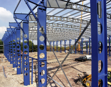
The relatively low self-weight of steel structures reduces material use and deliveries to site


[top]Sustainability
Energy costs and the reduction of operational carbon emissions are becoming increasingly important and sustainability is now a key issue within the planning process. In future, it is likely that planning permission will be easier to obtain with sustainable, environmentally friendly, solutions. Many clients, potential clients and occupiers have sustainability policies against which their performance is monitored by shareholders and the public.
Steel can be recycled any number of times without loss of quality or strength. Steel building components are fabricated under factory-controlled conditions with minimal waste (off-cuts are recycled as scrap). As the site activity is mainly assembly, there is rarely any waste on site.
Steel structures, particularly the relatively simple structures commonly used in single storey buildings, can be easily dissembled. The steel members may be reused in other structures – portal frames and similar structures are frequently dismantled and used at other locations. Recycling and reuse are key features of the circular economy.
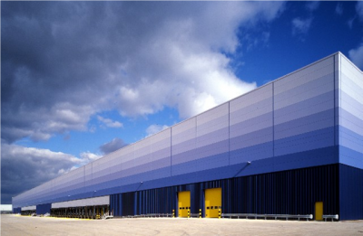
The Blue steel building in Leeds is shown before and after refurbishment to bring it up to current standards in terms of functionality and envelope performance.
- Blue steel building in Leeds
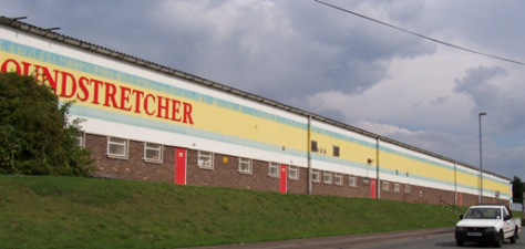
Before....
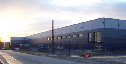
.....and after refurbishment


In addition to re-cladding the building using composite steel panels, the height of the building was increased by 3m by introducing column splices (as shown ) before re-erecting the original bracing, rafters and purlins; a great example of adaptable and reusable steel buildings.

[top]Value for money
The dominance of steel in this sector demonstrates the value for money that steel construction provides. This is primarily due to the increasingly efficient use of the portal frame by design and build steelwork contractors, improved project planning, and active supply chain management by main contractors. Information on the cost of structural steelwork generally and cost planning for industrial buildings specifically is readily available.

[top]Anatomy of typical single storey building
Main article: Concept design, Trusses, Portal frames, Building envelopes

Single storey buildings are usually required to provide large open floor areas, with few internal structural columns, thus offering maximum flexibility in use and freedom for activities that involve moving plant and equipment inside the building. These requirements are most often achieved by using a relatively light structural frame spanning from one side of the building to the other, clad with a weathertight envelope. The design of the structural framework and the envelope are closely linked.
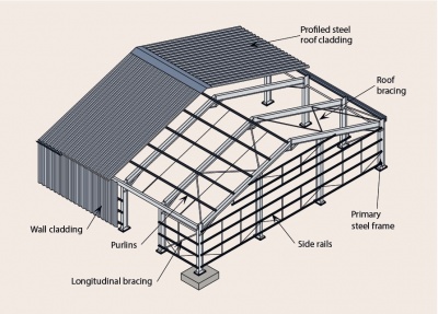
The schematic arrangement of a typical single storey building showing both the structural frame and the building envelope is provided. There are essentially three layers to the structure:
- The primary steel frame, consisting of columns, rafters and bracing. The example shown is a portal frame, however, it is equally applicable to other types of structural frames.
- The secondary steelwork, consisting of side rails and purlins for the walls and roof respectively. These members serve three purposes:
- The roof and wall cladding, whose functions include some or all of the following:
- Separating the enclosed space from the external environment
- Transferring load to the secondary steelwork
- Restraining the secondary steelwork
- Providing thermal insulation
- Providing acoustic insulation
- Preventing fire spread
- Providing an airtight envelope
- Providing ventilation to a building (ventilated or unventilated roofs and walls).

The cladding will also normally include ancillary components such as windows, rooflights, vents and gutters.
In most cases both building length and building width are much larger than the height of the building. Single-bay and multi-bay buildings can be used depending on the overall size of the building. A multi-bay portal frame is shown.
Overview of single storey industrial steel buildings
[top]Framing options
There are two main framing options for single storey industrial buildings:

The vast majority of single storey, steel framed buildings are portal frames. These were first widely used in the 1960s. During the 1970s and early 1980s they developed rapidly to become the predominant form of single storey construction. Using plastic design techniques first developed at Cambridge University, for spans up to about 50m portal frames are the most economical solution available. Large column-free areas can be achieved at relatively low cost. Often on multi-span frames the intermediate valley columns are omitted (‘hit-and-miss’) so that on, say, a 45m span frame, with bay centres of 8m, each column-free ‘box’ covers an area of over 700m2, which is nearly a fifth of an acre!
Portal frames typically use hot-rolled beams and columns for the roof rafters and supporting columns, although cold formed sections may be adequate for some small span structures. Portal frames come in a variety of different shapes and sizes, with flat and pitched roofs. The schematic arrangement of a typical single storey portal frame building is shown.


A small number of steelwork contractors offer portal frames made wholly from plates, often to form a tapered rafter section, which more closely follows the load profile on the steel member. The extra fabrication cost involved is offset by savings in the material content of the resultant frame. However, overall this form of frame has not been successful in the UK, mainly due to the efficiency of steelwork contractors offering parallel flange beam solutions.
Sophisticated computer software is widely available to design portal frames to the optimum efficiency. These programs use plastic or elastoplastic design techniques, and can handle multi-span frames with varying geometries and multiple load cases. Design is carried out to both to BS 5950[1], and BS EN 1993-1-1[2]. Detailed guidance on design to BS 5950[1] is given in SCI P252, and guidance on design to BS EN 1993-1-1[2] is given in SCI P399.

The main alternative to portal frames is lattice construction. Lattice trusses are generally more expensive than portal frames for routine applications and spans. However, for certain applications they will offer the best framing solution, such as: for very large spans (greater than 50m), for production facilities needing heavy plant suspended from the roof area, or where deflection criteria are particularly critical.
Trusses are a triangulated assembly of members usually either rolled or structural hollow sections. The internal members can be angles, beams or hollow sections, depending on the design loads, configuration and fabrication costs. Two basic configurations are used in single storey buildings – pitched roof trusses and ‘flat’ trusses of near uniform depth. Trusses are usually planar and will generally require bracing of some form to provide stability. As an alternative, three-dimensional trusses can be created.
Trusses typically have a greater depth than single beams or plate girders. The deflection of a truss is modest, and can be controlled, making them especially suitable when significant loads have to be supported from the roof structure, or when a flat (or nearly flat) roof is to be provided. The larger depth of the trusses increases the dimensions of the façade, but also provides space for services to be placed in the roof structure instead of below.
The weight of a trussed roof structure per unit area of roof is, in general, less than that of single beam girders, but the fabrication costs are higher. Trusses may be exposed in the completed structure, which may increase the fabrication costs if, for example, hollow sections are used for the members.
Cable stayed roofs
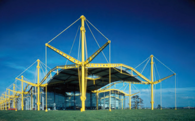
In a cable-stayed structure, tensile members (wire ropes or bars) are provided to give intermediate support to members such as roof beams, thus allowing those members to be reduced in size. The stays need to be supported by columns or masts and those members need to be anchored or braced with other stays. The bracing arrangement is usually very conspicuous and the aesthetics of the building must be considered carefully. An example of a cable stayed building structure is shown .
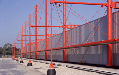

As most of the structure is outside of the building, maintenance costs can be high for this form of construction. Care must be taken in detailing the waterproofing where the stays pass through the envelope.
[top]Geometry and layout
Column positions may be restricted to suit the layout of equipment inside the building, such as racking in a warehouse, or machinery in a production unit. A good understanding of the costs of portal frames and the impact of different span and bay centre options is crucial to achieve an optimum building layout. Good advice can be obtained from steelwork contractors specialising in single storey buildings.
With increasing spans the unit structural cost falls gradually to a minimum at a span of around 30-35m. Above this distance costs start to increase quickly. Graphs can be produced for differing bay centres and height combinations to optimise the layout. The range of combinations escalates quickly, and the steelwork contractor will need to run a number of alternative designs to identify the best layout for the proposed building.
The height given in the performance specification should normally be specified to the underside of the roof steelwork, which in the case of portal frames is the underside of the haunch at the point where it meets the column. This is the clear height required by the building’s operator, and allows the steelwork contractor to design a frame to clear this level, the top of the column being determined by the total depth of the steelwork in the haunch area.
Column bases are typically set about 450mm below finished floor level, although this may vary on sloping sites or to suit door details.
The layout and design of the structure will also need to take full account of the required speed of erection. Decisions made at this stage will have a large impact on the number of work fronts available to the erectors, so the overall layout of the building may need to be changed if a particularly quick site programme is required.
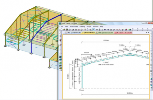
As a guide to steelwork sizes, on a typical 36m span multi-span frame, with a height to underside of haunch of 12m, one might see portal rafters 457mm or 533mm deep, the portal legs 686mm deep and a total steelwork weight of about 35 kg/m2.
[top]Secondary steelwork
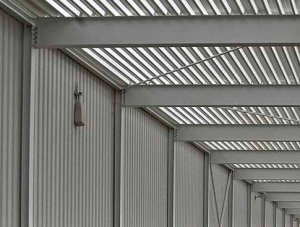
One feature of single storey buildings is the relatively high proportion of the steelwork that is cold rolled. Roof purlins and side rails for supporting roof cladding sheets and vertical cladding respectively are available as proprietary products from a number of manufacturers, for incorporation into the steelwork project. Although these items are very light, weighing only a few kilograms per metre, they typically account for 15-25% of the total weight of the steelwork in the building.
There are many more pieces of cold rolled steel than hot rolled (main) steelwork to erect and therefore this element of the erection needs to be carefully planned and controlled.
Secondary steelwork
[top]Envelope

All buildings, whatever their use, must provide a controlled internal environment that is protected from the variable and uncontrollable external climate. The required internal environment will depend on the intended use of the building and this will determine the specific requirements for the building envelope. Regulatory requirements under Part L of the Building Regulations are also forcing significant attention on the design and construction of building envelopes.
Generating and maintaining a controlled internal environment is a complex process, requiring a combination of mechanical and electrical services to heat and/or cool the building and a well-designed building envelope to regulate the heat gain and loss.
In addition to forming the building envelope, the roof and wall cladding may also have an important role to play in the structural performance of the building, by providing restraint to the secondary steelwork. Where such restraint is assumed (as is often the case in the purlins and side rails manufacturers’ load/span tables), it is essential that the cladding is capable of providing this restraint in practice.
The most common types of cladding used in single storey industrial buildings are ‘double skin’ systems comprising two metal sheets with a layer of insulation between. Double skin metal systems can be divided into four basic categories:
These are shown below.
- Metal cladding systems used in single storey buildings


[top]Floor slabs
In most cases, the floors of single-storey industrial buildings are used for vehicles, heavy machinery and racking systems. They are designed to support heavy loads and have to be ’flat’. Concentrated loads due to vehicles, machines, racking and containers have to be considered, depending on the application and local thickening of the slab can be undertaken if the configuration of any heavy machinery, etc. is known at the design stage. Most industrial buildings have a concrete floor with a minimum thickness of 150 mm on top of a layer of granular fill, which is also at least 150 mm thick. For large floor areas, a sliding layer between the base layer and the concrete is required, typically using two layers of synthetic material.
[top]Office areas

In almost all cases, there will be offices incorporated into the development. These are typically two storeys high, generally either within a corner of the building, or attached to the front and side elevations. The office floor area is usually about 5% of the total area of the building, but is dependent on the client’s or tenant’s specific requirements.
Most of the offices incorporated into industrial buildings are designed to conform to normal commercial standards and the envelope may be curtain walling rather than a steel sheet based system.
In multi-storey office areas, suspended floors are commonly composite floor slabs with in-situ topping or precast units. The choice will often depend on the programme and construction process selected by the main contractor.
Although the office areas are usually very much smaller than the remainder of the building, its construction involves many more trades and is consequently often the most critical area in terms of the overall construction programme.
[top]Mezzanines
Mezzanine floors in single storey industrial buildings offer the flexibility of providing additional floor space without extending the overall size of the building. They can be part of a new building construction, or as an upgrade to an existing building. Mezzanine floors tend to be separate steel framed structures which are supported directly off the ground floor concrete slab and tied into the main structural framing of the building. However, in industrial buildings it may be a requirement that uninterrupted working spaces are provided over the whole of the ground floor area (support forklift traffic). In these cases the mezzanine floor structure can be supported directly off the roof main framing members, thereby providing an unobstructed area underneath. Typically mezzanine floors are lightweight open grid floors. To restrict the loss of headroom to a minimum, cellular beams can be specified which will allow services to be provided within the depth of the mezzanine floor beams. A typical mezzanine floor in an industrial facility is shown.

[top]Forms of construction
Main article: Trusses, Portal frames
[top]Choice of building form
A single large hall is the main feature of most industrial buildings. The construction and appearance of a single storey industrial building provides the design engineer with a wide range of possible configurations in order to realise the architectural and functional requirements of the building. Generally, an industrial building has a rectangular foot-print, which is extendable in its long direction. The design of the building has to be coordinated with its functional requirements and its operational energy performance, including lighting.
A comparison of the benefits and the reasons for choosing a particular building form (simple beam structure, portal frame or truss) is shown in the table.
| Simple beam/column | Portal frame | Truss |
|---|---|---|
| Advantages | ||
| Simple design | Long span | Very long spans possible |
| Designed to be stable in-plane | Heavy loads may be carried | |
| Member sizes and haunches may be optimised for efficiency | Modest deflection | |
| Disadvantages | ||
| Relatively short span | Software required for efficient design | Generally more expensive fabrication |
| Bracing needed for in-plane stability | Limited to relatively light vertical loading, and modest cranes to avoid excessive deflections | Generally bracing is used for in-plane stability |
| No economy due to continuity | ||
[top]Types of portal frame
Portal frames are the most commonly used type of structural frame for industrial buildings because they are a highly cost-effective solution. They are widely used because they combine structural efficiency with functional application. Various configurations can be designed using the same structural concept as shown. Multi-bay frames can also be designed, as in (e) and (f), using either single or pairs of internal columns.
- Various forms of portal frames

(a) Portal frame – medium span

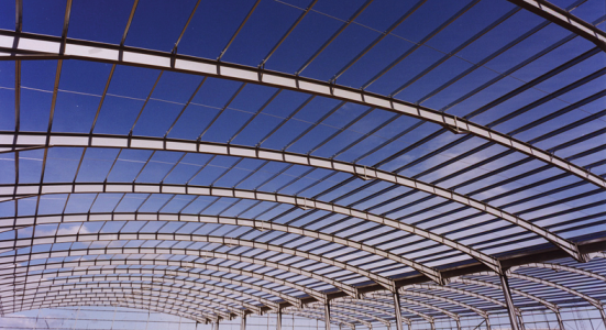
(b) Curved portal frame

(c) Portal frame with mezzanine floor

(d) Portal frame with overhead crane


- Various forms of portal frames

(e) Two bay portal frame

(f) Portal frame with integral office


These simple types of structural systems can also be designed to be architecturally more appealing by using curved members, cellular or perforated beams etc. Innovative structural systems have also been developed in which portal frames are created by moment resisting connections using articulations and ties.
[top]Lattice structures
Long-span industrial buildings can be designed with lattice trusses, using channel, beam or tubular sections. Lattice trusses tend to be beam and column structures and are rarely used in portal frames. Various configurations of lattice trusses are illustrated. The two generic forms are W or N bracing arrangements. In this case, stability is generally provided by bracing rather than rigid frame action.
Using lattice structures, a comparatively high stiffness and load bearing resistance can be achieved while minimising material use. Besides the ability to create long spans, lattice structures are attractive and enable simple service integration.


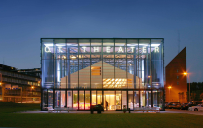
[top]Suspended structures
By using suspended structures, long span buildings with high visual and architectural quality can be realised. The division into members that are predominantly subject to either tension or compression permits the design of lightweight structures. However, structures that save on materials use do not necessarily lead to economic solutions. Particularly in space structures, the joints may be very complex and more time consuming to construct and install. Therefore, possible applications of this type of structure are industrial buildings that also serve architectural purposes rather than merely functional buildings.
[top]Design
Main articles: Concept design, Trusses, Portal frames, Modelling and analysis, Member design, Operational carbon, Single storey buildings in fire boundary conditions, Simple connections, Moment resisting connections
Steel construction is one of the most efficient sectors in the construction industry. Leading suppliers manufacture the components offsite, using computer controlled equipment driven directly by information contained in 3D computer models used for detailing. In addition to driving the manufacturing process, the information in the model is also used for ordering, scheduling, dispatch and erection. Single storey construction at its best, with its highly integrated design and manufacture, represents excellent levels of efficiency. The key to realising the highest level of efficiency is to work in a way that enables the optimum use of this infrastructure.
[top]Design concept
The development of a design solution for a single storey building, such as a large enclosure or industrial facility is more dependent on the activity being performed within the building (and possible future requirements) than other building types. Although single-storey buildings are primarily functional, they are often designed with a strong architectural input dictated by planning requirements and client ‘branding’.
The following overall design requirements should be considered at the concept design stage of single storey industrial buildings:
- Space use, for example, specific requirements for handling of materials or components in a production facility
- Flexibility of space in current and future use
- Speed of construction
- Environmental performance, including services requirements and thermal performance
- Aesthetics and visual impact
- Acoustic isolation, particularly in production facilities
- Access and security
- Sustainability considerations
- Design life and maintenance requirements, including end of life issues.
To enable the concept design to be developed, it is necessary to review these considerations based on the type of single storey building. For example, the requirements for a distribution centre will be different to those for a manufacturing facility. A review of the importance of various design issues is presented in the table for common single-storey industrial building types. Retail and leisure building requirements are described specifically in the sector specific sections of the website.


[top]Frame choice
The most popular choice of structural form for single storey buildings with spans of 20 to 60m is the portal frame because of its excellent structural efficiency and ease of fabrication and erection. Portal frames may be designed using elastic or plastic analyses and design. Elastically designed portal frames are likely to be heavier, as they do not fully utilise the capacity of the sections, but are simpler to design and detail using non-specialist design software.
For longer spans, lattice trusses may be used to advantage instead of portal frames. Trusses are likely to be more efficient for spans over 60m and in buildings of shorter spans where there is a significant amount of mechanical plant.
[top]Structural design
Efficient portal frames with relatively low roof loads are slender structures and in some cases, the slenderness is such that second-order effects need to be considered, when analysing the structure. Generally, second order effects must be considered for the Ultimate Limit State (ULS), but will have negligible effects at the Serviceability Limit State (SLS).
Portal frames provide sufficient in-plane stability, and thus only require bracing for out-of-plane stability. However, their structural efficiency depends on the method of analysis, and the assumptions that are made regarding the restraint provided to the structural members.
| More efficient | Less efficient |
|---|---|
| Analysis using elastic-plastic software | Elastic analysis |
| Cladding considered to restrain the flange of the purlins and side rails | Purlins and side rails unrestrained |
| Purlins and side rails used to restrain both flanges of the hot-rolled steelwork | The inside flange of the hot rolled steelwork is unrestrained |
| Nominal base stiffness utilised | Nominal base stiffness ignored |
The most economical structures are often those produced using plastic design techniques, which in the UK, are well established and have been used for over 40 years.
Lattice trusses are typically designed using elastic analysis techniques.
The ‘screen grab’ below is of a Fastrak model of a portal-framed building.

[top]Interdependence of frames and envelopes
The structural efficiency of portal frames is partly due to the provision of restraint to the rafters and columns by the purlins and side rails respectively. Similarly, the efficiency of the purlins is dependent on restraint provided by the cladding. The cladding sheets are profiled to provide the necessary strength to span between the purlins and provide the required restraint. The profile has also to accommodate storm water run off. Designers and contractors should note that good interaction between the frame and envelope components is essential for structural efficiency and, for this reason, the cladding must be fixed to all purlins and rails in accordance with the manufacturer’s recommendations.
[top]Operational energy performance

(Image courtesy of BSRIA)
Driven by Part L of the Building Regulations, the required reductions in U-values over recent years have led to a considerable increase in insulation thickness, with possible implications for frame stability, cladding weight and consequential handling requirements. There is a common perception that this trend will continue indefinitely as regulatory changes increase the demands on the building envelope. However, in reality the relationship between insulation thickness and energy efficiency is subject to a law of diminishing returns and the point is now close to being reached where further increases in insulation thickness are unlikely to yield significant improvements in operational energy performance, a fact recognised in a 2012 consultation[3].
For many applications, the inclusion of roof lights is important because they reduce the amount of artificial lighting that is needed and, consequently, the energy demands of the building. However, they also increase solar gain, which can lead to overheating in summer and increase cooling demand. Heat loss through thermal bridging also becomes more significant (relatively) as the insulation thickness increases, requiring the use of enhanced construction details and specialised components in order to satisfy regulatory requirements.
A balance of all the factors is necessary to optimise the reduction of carbon emissions in the operation of any building.

The introduction of mandatory airtightness testing has highlighted the importance of designing and delivering a building that is not ‘draughty’. Recent studies have demonstrated that controlling airtightness is a very effective way of improving energy conservation. As an example, while the current minimum standard for airtightness of buildings >500m2 is 10m3/m2/hr at 50 Pascals, levels of airtightness down to a tested value of 2m3/m2/hr are possible with standard construction. However, achieving this level depends on an assured quality of construction and detailing. For buildings with floor areas less than 5000 m2 achieving good levels of airtightness becomes difficult to achieve due to the higher proportion of openings relative to the envelope area. While a common view is that airtightness is the responsibility of the cladding contractor, in reality the necessary quality of construction can only be achieved if all parts of the supply chain understand the requirements and the building design is well coordinated.
Lighting
Requirements for the lighting of industrial buildings depend on the type of building, its use and occupancy pattern. The concept and arrangement of openings to provide natural lighting permit diversity in architectural design. Rooflights and gable glazed roofs are common, along with lightbands in the façade. Openings for natural lighting can serve as smoke and heat outlets in case of fire. In the UK, single storey industrial buildings typically have rooflights comprising 10 – 15% of the roof area.
Well-designed natural daylighting can have a significant impact on a building’s operational carbon emissions. However, too much natural daylighting can result in excessive solar gain in the summer, leading to overheating, and increased heat loss through the envelope in the winter.
One factor which has a major impact on the efficiency of lighting large single-storey industrial buildings (both natural and artificial) is the use of high bay shelving or racking. Once obstructions such as high bay racking are installed, the building is effectively split into a number of narrow, corridor-type spaces which require many more fittings, and hence more energy, to achieve the same level and uniformity of lighting. If known at the design stage, the configuration of racking should be taken into account in the design of rooflights and artificial lighting systems.
The decision to utilise natural daylight within a building and the type of day-lighting selected have important implications for the overall building design. It is discussed in detail in the Target Zero Warehouse guidance
[top]Service integration
For industrial buildings, special requirements for building services are often defined, which may be necessary for the operation of machines and manufacturing lines. The service integration should be taken into account in the early planning stages. In particular, the position and size of ducts should be coordinated with the structure and any provisions for natural lighting. The use of structural systems, such as cellular beams and trusses, can facilitate easier integration of services and help to achieve a coherent appearance of the building.
The design of the servicing machinery and rooms can be of major importance in industrial buildings. Centralisation of the building services can offer the advantage of easy maintenance. In large buildings, service runs can be very long and, particularly for ducts at roof level, expansion and movement of the ducts should be considered and taken into account.
Natural ventilation reduces the reliance on air conditioning systems, which in turn means a reduction in the building’s operational carbon emissions. The effectiveness of natural ventilation depends on the size and orientation of the building. Roof vents are a common option for natural ventilation in buildings without suitably large openings, however these need to be carefully positioned so as to maximize their performance. Hybrid ventilation systems are now popular in industrial buildings. They use predominantly natural ventilation, but with mechanically driven fans to improve predictability of performance over a wider range of weather conditions.
[top]Roof drainage systems

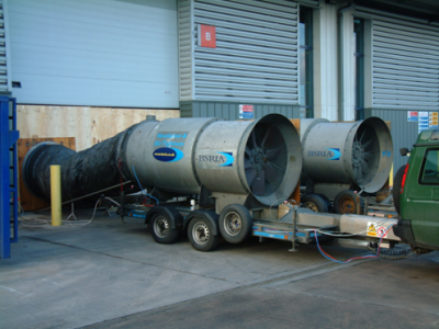
(Image courtesy of A.C.Bacon Engineering Ltd.)
The design, detailing and erection of gutters is often neglected. Those involved in the design of the supporting steelwork are often not aware of the impacts arising from the introduction of insulated gutters and symphonic drainage systems. The weight of the gutter, both in terms of the handling difficulties during installation and the strength and serviceability of the supporting structure, is such that it requires specific attention. Attention is necessary to the fixing details so that they can readily be attached to and restrain the supporting members. It is also good practice to include a secondary drainage system to avoid flooding into the building if the system clogs and fails. The gutter design should take account of the potential for flash floods and the fact that gutters have to be maintainable with good access for cleaning.
The image shows a typical roof drainage system used in single-storey industrial buildings.
[top]Floors and foundations
The structural engineer will normally be responsible for the design details of the foundations. The ground slab is usually designed and built by a specialist subcontractor working to a performance specification prepared by the consulting engineer. The design and construction details should be approved by the engineer prior to construction and the details must be coordinated with all adjacent trades.
There are innovations in the use of precast concrete bases, ground beams and such items as dock leveller surrounds and retaining walls, which are helping to increase the overall speed of construction. The detailed design of these items and the adjacent elements of structure and cladding has to be consistent with both the construction sequence and the need for access and handling.
The structural engineer has to determine whether nominally pinned or nominally fixed bases are appropriate for the steel frame. A site investigation should be commissioned and information obtained on the anticipated ground conditions. The decision on appropriate foundations will be based on this information and should be passed to the steelwork contractor as the basis for his design.
With regard to the ground floor slab, the Concrete Society technical report TR34[4] sets out good practice for design and construction, including advice on tolerances, loadings, finishes, joints, sub base, a variety of alternative construction methods and necessary maintenance measures.
The slab is generally laid after the cladding has been erected, which means that it should not be affected by weather and dust. If acceptable methods can be developed, construction can be accelerated by casting the slab prior to erection of the envelope.
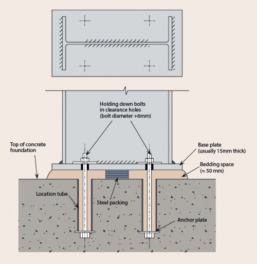
[top]Connection details
The three major connections in a single bay portal frame are those at the eaves, the apex and the column base.
For the eaves, bolted connections are mostly used as shown in the figure below.
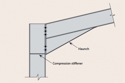

The apex connection is often designed similarly.
The base of the column is often simple with larger tolerances to facilitate the interface between the concrete base and steelwork. Pinned connections are typically preferred as they enable smaller foundations to be designed, however, stability during construction needs to be considered as must whether the column is in a boundary condition.

[top]Fire Safety
Single storey buildings are not usually required to have fire resistance. The most common, but not the only, situation where fire resistance is required is when fire spread between buildings is of concern. This is the well known boundary condition. Where this occurs, it is normally only the external wall close to adjoining buildings and its supporting columns that requires fire resistance. The rafters and any columns not considered to be in a boundary condition are left unprotected. The bases of the protected columns must be designed however to resist the overturning moment cause by the collapse of the rest of the structure.
[top]Sustainability
In the context of modern industrial buildings, the principal sustainability issues to address include how to minimise operational energy use (and associated carbon emissions), particularly in the heating and lighting systems, how to achieve high BREEAM ratings and any specific planning requirements.
Significant interest is also being shown in the integration of low and zero carbon technologies into industrial buildings, particularly technologies that exploit their large envelope areas, such as photovoltaics and transpired solar collector technologies (TSCs).
[top]Operational energy use in single storey industrial buildings
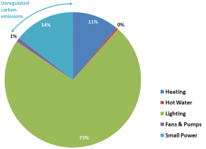

The breakdown in operational carbon emissions by energy use in a typical, large single-storey industrial building, in this case a distribution warehouse, is shown.
Lighting is by far the most significant energy demand accounting for, in this case, around three quarters of the total operational carbon emissions. Consequently efficient lighting systems coupled with optimum rooflight design are key in delivering operational carbon reductions. The complexity of the interaction between rooflight design, lighting systems, daylight dimming (and racking when dealing with warehouse buildings) requires detailed dynamic thermal simulations in conjunction with good lighting design to develop an optimum lighting solution. Guidance on the optimum area of rooflights in industrial buildings is given in the Target Zero guide.
Significant reductions in operational carbon emissions are achievable in industrial buildings using energy efficiency measures particularly measures relating to lighting. Significant further reductions are achievable via the use of solar photovoltaic and transpired solar collector (TSC) technologies which take advantage of the large roof and wall areas of industrial buildings. The viability of such technologies is strongly dependent on the cost of technology and particularly subsidies such as Feed-in tariffs and the Renewable Heat Incentive (RHI).
The Target Zero project provides in depth guidance about how to achieve low and zero operational carbon targets in single-storey buildings. Guidance is also available on External links
[top]BREEAM for industrial buildings
The BREEAM environmental assessment scheme provides a method for quantifying the environmental performance of buildings. Although the scheme is voluntary, many commercial sector clients are responding to demand and adopting BREEAM to deliver buildings which are low energy, sustainable and future-proofed.
Results from the Target Zero programme suggest that for a single-storey industrial building, the increase in capital cost (from a Part L 2006 compliant base case) to achieve the following BREEAM (2008) ratings is:
- 0.04% to achieve BREEAM ‘Very Good’
- 0.4% to achieve BREEAM ‘Excellent’
- 4.8% to achieve BREEAM ‘Outstanding’.
More details are given in theTarget Zero guide and guidance is available by following External links
[top]Construction
Main articles: Construction, Fabrication, Health and safety
[top]Lead-in times
The period from receipt of instruction (letter of intent or order) to arrival on site varies depending on project size, complexity and the industry’s workload levels. As a guide, for a typical small or medium-sized industrial building (up to 10000m2) a lead-in of 8 weeks would be normal, extending to 10-12 weeks on bigger projects. These periods can often be improved if especially required on individual projects by discussion with the steelwork contractor.
[top]Site erection periods
The speed of erection will depend on a number of factors:
- Number of erection gangs – an erection gang usually consists of 3 or 4 men, with a crane and mobile elevated working platforms. As a rule of thumb, working an eight hour day in reasonable weather, a gang will erect about 50 tonnes (hot and cold rolled) per 5 day week. This is roughly equivalent to an area of 1500m2. The overall speed of erection will depend on the resources available to the steelwork contractor in terms of speed of the supply of steelwork to site, the number of erection gangs at his disposal, and the number of work fronts that can be safely and efficiently worked concurrently.
- Time of year – in the depths of winter daylight hours are restricted, and it is not possible to work the same number of hours as in the summer months, when it may be possible for the erectors to work much longer days.
- Weather – the programme needs to build in a sensible allowance for weather, based on the time of year planned for erection of the steelwork.
- Site conditions – the planned programme will not be achievable in the absence of well prepared and safe ground. Even if deemed safe for work, poor ground will result in a serious loss of productivity for the erection process. This important aspect is developed further in safe site erection.
- Site planning – fast programmes will require large lay down areas so that steelwork can be delivered and offloaded in the desired location prior to the erection gang reaching that area.
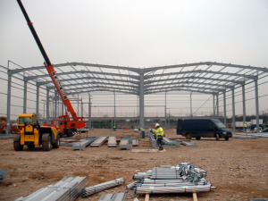
[top]Safe site erection
Erection of the structure is generally undertaken using mobile telescopic cranes and Mobile Elevating Working Platforms (MEWPs), often referred to as ‘cherry pickers’. Wall cladding is usually installed using scissor lifts. A key health & safety issue for the erection of single storey industrial buildings is the condition of the site. MEWPs are very efficient and offer the ability to safely access all areas of the structure, but their success is highly dependent on the ground conditions. Poor or badly prepared ground will deteriorate rapidly once a MEWP begins to move over the site and therefore it is important that the main contractor designs and prepares the ground to take these loads.
Normally the whole of the area of the building footprint will need to be prepared for MEWP and mobile crane access. Additionally, to fit the cold rolled side rails, a 3–4m wide strip for MEWP access will need to be provided around the external perimeter of the building.
Before commencement of erection, the steelwork contractor will ask the main contractor to complete and sign the BCSA’s Safe Site Handover Certificate. This essential document sets out in a checklist form the matters needed to ensure a safe site for steelwork erection.
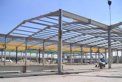
Telescopic crane and scissor lift
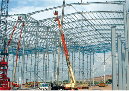
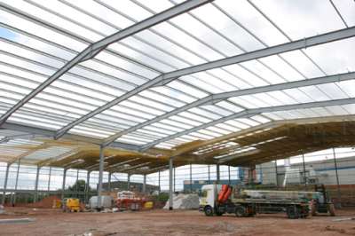
Construction of a modern portal frame building


[top]Envelope erection
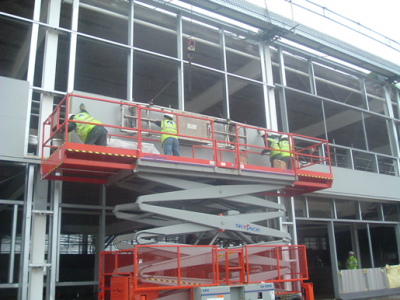
The greatest risks during building envelope (cladding) erection are those activities associated with operatives working at height and materials falling from height. Particular attention needs to be paid to both of these issues in terms of providing a safe working platform from which the cladding operations can take place, a suitable means of access and egress, and effective barriers to prevent falls of either people or materials. Wall cladding erection is generally carried out from cherry pickers or scissor lifts which provide safe access and a safe working platform.

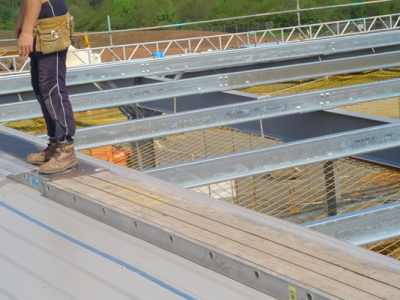
Risk to workers during roof construction is minimised by providing several important safety features:
- Temporary boarding and platforms spanning between purlins
- Safety nets
- Perimeter edge protection (guard rails and toe boards).
More details are available on safe erection here.

[top]Procurement
Although there is a proliferation of procurement processes in general construction, there are only two processes in common use for industrial buildings: ‘Design and Build’ and ‘Traditional’. Of these, ‘Design and Build’ has by far the largest share of the market with at least three quarters of single-storey industrial buildings constructed using this method. This situation has evolved because:
- The product, i.e. the building, is relatively simple when compared to other types of buildings
- There are well-developed systems for all parts of the construction, i.e. primary and secondary steelwork and envelope systems
- The client brief can be set out in a relatively straightforward manner
- The size of the market has attracted many competent companies to develop systems and offer their services.
The decision as to which process to employ depends on the relative importance of maintaining control of the design process and the competitive edge offered by Design and Build. Of particular note are the different responsibilities of the various parties in the different contract arrangements.
[top]Design & Build
The prime attraction for the client of the Design and Build process is that the risks are passed to a contractor, who is responsible for all the design and construction aspects. The contractor’s role is to manage all of the activities and ensure the quality of the completed building. The work is carried out to a Performance Specification that normally includes information such as an outline of the project, architect’s drawings, loading requirements, time to first maintenance for painted steelwork, and descriptions of other trades such as cladding materials and industrial doors. This situation works well in the industrial buildings sector because there are sufficient companies within the sector that have the relevant competence and financial strength from which clients can select their team.
A number of steelwork contractors specialise in this market, and they are able to produce very economical frames, with short lead times and fast erection periods. Detailed knowledge of steel availability and relative costs, means that economical frames can be selected, purposely designed to suit the specialist steelwork contractor’s own production facilities, and to make site erection safe and efficient.
Many large clients with significant repeat business have developed good relationships with a relatively small number of steel construction supply chains, who have become accustomed to working with each other in informal and trusting partnership arrangements. This has proved extremely beneficial to all parties involved.
An important ingredient in Design and Build relationships that tends to develop over a considerable period is that of trust between the parties. This may be difficult to achieve in new situations, but it should be a major objective. The working arrangements and form of contract selected should be such that they encourage and reward helpful behaviour. This generally requires communications of all kinds to be as transparent as possible.
Despite passing much of the risk and responsibility to the contractor, the client retains overall responsibility for Health & Safety. The appointment of experienced, responsible contractors and specialist contractors is an essential part of this duty.
[top]Traditional
The alternative to ‘Design & Build’ is the traditional approach, with the structural design being carried out by a consulting engineer working for either the client or the main contractor. The consultant also prepares the steelwork general arrangement drawings, showing all the key dimensional information. Once designed and drawn, the steelwork is tendered to steelwork contractors. The contract will include for connection design, detailed fabrication drawings, fabrication, delivery and erection. This procurement route is sometimes chosen because it gives greater perceived control over the project, although it is rarely going to achieve the competitive edge available through the ‘Design & Build’ route.
The main contractor, who is selected through a competitive tendering process, is responsible for constructing the works according to the information provided by the design team. Much of the construction work, including the erection of the steel frame and installation of the cladding, is likely to be carried out by specialist subcontractors.
The traditional approach tends to be used for specialised buildings, since the architect, and hence the client, retains more control. Some elements of the building, notably the frame, may be procured through a limited 'Design and Build' process.
[top]Project management
The preparation of the detailed build programme for the overall project is normally the responsibility of the main contractor.
Most single-storey buildings now have ‘fast-tracked’ programmes. In the case of steelwork, this means that following trades such as roof and wall cladding, brickwork and doors will be starting whilst steelwork erection is progressing further down the building. To achieve this type of programme, it is necessary to have a series of sectional handovers of the steelwork, at (say) two week intervals down the building. Each section is fully erected, and then lined and plumbed. After checking and approval by the main contractor, the steelwork bases are grouted up, after which the following trades can commence.
The build sequence at major interfaces is particularly important for the steelwork contractor. For example, the base of the door posts may be bolted to a pre-cast concrete ring beam. Ideally therefore the ring beam should be in place before steelwork erection; otherwise it will be necessary to leave out the door steelwork and associated sheeting rails until the ground beams are fixed. Careful planning and good design co-ordination will in most cases eliminate the need for steel components to be omitted, allowing the programme to proceed smoothly. However, in some cases, a second fix of steelwork will be unavoidable. It is essential that these cases are clearly identified in advance, and allocated a suitable duration in the build programme. The steelwork contractor can then organise erection labour accordingly, and may choose to keep the second fix steelwork off-site until required, avoiding site loss or damage to the un-fixed components.
[top]Early involvement of the supply chain
In most cases, an architect is commissioned to produce the concept designs and obtain the necessary planning permissions together with sufficient information to obtain tenders from contractors and select the successful bid. The pre-contract period should be used to sort out the design responsibilities, the key roles which will be played by the project participants and their employees and the skills required to perform these roles. These factors may influence the choice of contractors.
Once a main contractor has been appointed, he becomes responsible for all design and construction activities in the project, although it is common to employ specialist subcontractors to carry out the actual construction work. The architect who produces the concept design is often subsequently novated to the selected main contractor, together with the engineer who initially appraises the ground conditions and drainage if this has not been done already.
The main contractor has to manage all the interfaces between the various elements of the work. This coordination role is very important and can be undertaken in-house, although in many cases he will pay an architect to act on his behalf.
It is noteworthy that with experienced and knowledgeable clients, the specifications tend to be thinner documents that make use of trusted manufacturers’ recommendations. Less experienced clients and their advisors tend to produce thick specifications that aim to defend against failure rather than encouraging energy to be spent in ensuring that all goes well. This may be a reflection on the earlier state of the relationships, but there is a growing body of successful firms which can testify to the benefits of encouraging success.
The progressive approach does require greater engagement by all concerned rather than the attitude of “go away and sort it out amongst yourselves”. As in all aspects of life, caring attitudes are infectious.
[top]Selection of the supply chain
It is important therefore to work with people who have demonstrated that they can deliver predictably in terms of cost, time and quality. This is a familiar list of attributes, but the will to work collaboratively is an important addition.
The selection of the supply team is critical but not always easy. Clients should select an architect and, where necessary, an engineer who is familiar with their business needs and the type of work envisaged. The appointment of the main contractor and specialist sub-contractors should be discussed between the client and his advisors who are already in place. Help is available from reputable trade associations such as the Metal Cladding and Roofing Manufacturers Association (MCRMA) and the British Constructional Steelwork Association (BCSA). The latter maintains a Register of Steelwork Contractors with guidance on the type and size of contracts for which they have the skills and financial stability.
[top]Achieving collaborative working
The preferred key players should be brought together by the contractor as soon as practicable. Initially, these players will be the architect, engineer and the steelwork and building envelope contractors.
In terms of stages in the contract there are two important factors. Firstly, the participants have to be certain they will be carrying out the work, even though, secondly, they will not be fully committed financially at this stage. This is important, because they must be free to bring ideas to the project, safe in the knowledge that the information will not benefit their competitors. However, the joint discussions with fellow suppliers might affect the detail and costs of their work package.
Cost reduction exercises are frequently part of the process, but the interdependence of the systems must be remembered by all and the knock on effects taken into account.
There will obviously be a more cooperative approach if the appropriate mechanisms are in place, rather than having to defend a fixed contract sum in which it may have been necessary to include some guesstimates of what to include at a detailed level. To achieve this end there are two possible approaches:
- A partial order to cover the work in stages.
- A letter of intent, but with recognition of the risks of cancellation incorporated.
Forward commitments need to include a recognition that suppliers have to manage the efficient use of their resources and, while they will undoubtedly be as cooperative as possible, it may be difficult to accommodate short term postponements in a busy schedule.
A key determinant of a successful project is the quality and timeliness of information. To achieve a quick lead-in and efficient working, it is necessary to have other major subcontractors appointed at the same time as the steelwork sub-contractor.

(Image courtesy of Severfield (Design & Build) Ltd.)
The main contractor has a major role to play in coordinating this part of the process. The interfaces between steelwork, roof and wall cladding, doors, glazing, pre-cast units, etc. will all need to be agreed. On a short lead-in project (say eight weeks or less), these dimensions will need to be finalised in the first two weeks. Recent amendment to the Building Regulations Part L, have resulted in particular care now being required in preparing details around the key interfaces in the external envelope to minimise heat loss and air permeability. Careful detailing and complete co-ordination of the steelwork and cladding contracts is necessary to achieve these objectives.
Many main contractors are addressing these issues by establishing a Strategic Supply Chain, selecting a small number of sub-contractors in each of the major specialist areas. By encouraging team working between members of the supply chain, it is possible to capture learning on one project and use it successfully on the next. A well run supply chain will result in greater efficiency of all its participants, producing better quality and lower costs as the team develops.
A series of quick-fire "Design Team meetings" in the critical early weeks, called and chaired by the main contractor, is the best way to co-ordinate the project design. All major specialist sub-contractors need to be present, together with the architects and other relevant professionals. When time is pressing, it is usually most effective for the key decisions to be taken at the meeting, rather than left to future meetings or for subsequent development.
[top]Achieving commitment
Through early design orientated meetings, financial commitment can be finalised on the basis of information which is consistent across the supply chain, knowing that all pertinent issues and opportunities for improving performance have been explored. The contract should provide a framework for resolving disagreements if something does go wrong rather than attempting and, probably failing, to ensure that problems do not occur.
Minimising the occurrence of problems is achieved through improving relationships between people. This is extremely difficult to achieve through the use of complex documents. People perform best when they are incentivised and want to perform well, not because a piece of paper says they ought to. Time spent defending a contract would be better spent improving the job. However, protection for all is needed as things can go wrong.
Construction is not exempt from the law of unintentional consequences. If trust is to be developed, it is important to ensure that agreements made by senior people in meetings are followed by actions in practice. Care is needed to ensure that those working at the detail level are fully conversant with the agreements reached and understand why they will improve the performance of the overall project.
The actions and attitudes of the people involved are most important and these will be determined by the company culture as much as by instruction. Partnership based procurement has been extolled by some and in time, it may be the situation to which industry should aspire. However, well run Design & Build is currently best practice and a good foundation on which to move forward.
[top]Case studies
- Wasdell Dundalk-2a.jpg
[top]References
- ↑ 1.0 1.1 BS 5950-1:2000 Structural use of steelwork in building. Code of practice for design. Rolled and welded sections. BSI
- ↑ 2.0 2.1 BS EN 1993-1-1:2005+A1:2014, Eurocode 3: Design of steel structures. General rules and rules for buildings, BSI
- ↑ 2012 consultation on changes to the Building Regulations in England. Section two, Part L (Conservation of fuel and power). Department of communities and local government
- ↑ TR 34 (4th Edition) Concrete industrial ground floors - A guide to design and construction, Concrete Society, 2016
[top]Further reading
- Steel Buildings, BCSA No. 35/03, Chapter 3, Single Storey Buildings
- Steel Buildings, BCSA No. 35/03, Chapter 22, Building Envelope
- Steel Designers' Manual 7th Edition. Editors B Davison & G W Owens. The Steel Construction Institute 2012, Chapter 4, Single Storey Buildings
[top]Resources
- SCI P252 Design of Single Span Steel Portal Frames to BS 5950:2000
- SCI P347 Single Storey Buildings – Best practice guidance for developers, owners, designers & constructors
- EP37 Best Practice in Steel Construction – Industrial Buildings, Guidance for architects, designers & constructors
- SCI P313 Single Storey Steel Framed Buildings in Fire Boundary Conditions
- SCI P346 Best practice for the specification and installation of metal cladding and secondary steelwork
- SCI P397 Elastic Design of Single-span Steel Portal Frame Buildings to Eurocode 3, 2013
- SCI P399 Design of steel portal frame buildings to Eurocode 3, 2015
- Target Zero: Guidance on the design and construction of sustainable, low carbon warehouse buildings, Tata Steel and BCSA
- Scheme development: Selection of the external wall envelope system for single storey buildings, SS019a-EN-EU
- Scheme development: Details for portal frames using rolled sections, SS051a-EN-EU
- Scheme Development: Design of portal frames using fabricated welded sections, SS052a-EN-EU
- Scheme development: Selection of the external roof envelope system for single storey buildings, SS018a-EN-EU
- Scheme development: Overview of structural systems for single-storey buildings, SS048a-EN-EU
- Steel Buildings in Europe - Single storey buildings:
- Part 1: Architect’s guide
- Part 2: Concept design
- Part 3: Actions
- Part 4: Detailed design of portal frames
- Part 5: Detailed design of trusses
- Part 6: Detailed design of built up columns
- Part 7: Fire engineering
- Part 8: Building envelope
- Part 9: Introduction to computer software
- Part 10: Model construction specification
- Part 11: Moment connections
- Steel Insight 6 – Industrial buildings, February 2013, Building magazine
- Steel Insight 12 – Cost update and case studies: Industrial buildings, March 2015, Building Magazine
- Steel Insight 18 – Cost update and case studies: Industrial buildings, October 2016, Building Magazine
- Guidance document GD 24 – Installation of purlins and side rails, MCRMA, January 2016
- Costing Steelwork 3 – Industrial Buildings, October 2017
Colorcoat® Technical Papers:
- The role of the building envelope in Part L 2010 compliance
- Acoustic performance of pre-finished steel cladding systems
- Creating an air-tight building envelope - RIBA approved
- Ensuring consistent appearance of pre-finished steel wall cladding
- Fire performance of pre-finished steel cladding systems
- Refurbishment solutions for non-domestic buildings
- Structural performance of built-up roofing and cladding systems – RIBA Approved
- The effect of gauge on pre-finished steel roof and wall cladding performance
[top]See also
- Building envelopes
- Thermal performance
- Portal frames
- Trusses
- The case for steel
- Sustainability
- Steel and the circular economy
- Cost of structural steelwork
- Cost planning - Industrial buildings
- Concept design
- Modelling and analysis
- Member design
- Operational carbon
- Single storey buildings in fire boundary conditions
- Simple connections
- Moment resisting connections
- Construction
- Fabrication
- Health and safety
[top]External links
- Metal Cladding and Roofing Manufacturers Association (MCRMA)
- National Association of Rooflight Manufacturers (NARM)
- Trimble