


Stiffeners
Stiffeners are secondary plates or sections which are attached to beam webs or flanges to stiffen them against out of plane deformations.
Almost all main bridge beams will have stiffeners. However, most will only have transverse web stiffeners, i.e. vertical stiffeners attached to the web. Deep beams sometimes also have longitudinal web stiffeners. Flange stiffeners may be used on large span box girder bridges but are unlikely to be encountered elsewhere.
Guidance on the design of stiffeners is given below and in Guidance Notes GN 2.04 and GN 2.05.
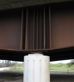

River Eden Bridge, Temple Sowerby Bypass
[top]Types of stiffener
There are two principal types of stiffener:
- Longitudinal web stiffeners, which are aligned in the span direction
- Transverse stiffeners, which are aligned normal to the span direction of the beam.
- Types of stiffeners
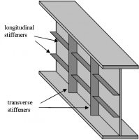
Stiffeners on I-section girders
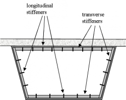
Stiffeners on box girders
Longitudinal and transverse stiffeners in a box girder
(Image courtesy of Atkins)


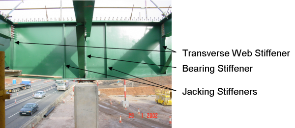
Transverse web stiffeners are usually provided at bearing positions and these are known as bearing stiffeners. For future maintenance it is good practice to provide bearing stiffeners at jacking points (for when girders have to be raised to free bearings for replacement). Other transverse stiffeners are called intermediate transverse web stiffeners.

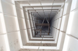
(Image courtesy of Arup)
Box girders usually have diaphragms at the positions of supports instead of stiffeners. These are usually solid plates across the inside of the box.
[top]Stiffener sections


A variety of sections have been historically used as stiffeners, however the simple flat stiffener is the type almost always used in modern designs. Stiffeners can be attached on one side of the plate (single sided), or on both sides (double sided). Usually bearing stiffeners are double sided, while intermediate web stiffeners are single sided. Stiffeners can also be doubled up, or even trebled, to form multi-leg stiffeners.
[top]What are stiffeners for?
Stiffeners have one or both of the following functions:
[top]Controlling local buckling
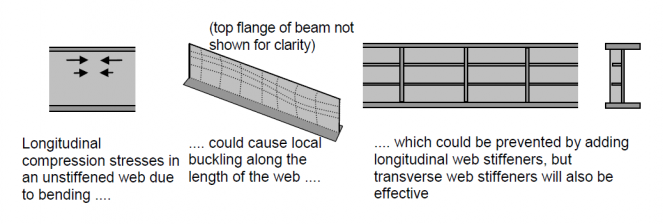
Local buckling occurs when a cross section is slender enough for buckling to occur within the cross section, due either to compression or shear. The webs of bridge beams are usually vulnerable to local buckling, but flanges are usually much thicker and inherently more resistant to buckling.
Local buckling can occur due to transverse compression load e.g. a web subjected to a bearing reaction, longitudinal compression load e.g. from bending, or from shear.
In all cases the addition of a relatively small stiffener to a slender plate can increase the resistance to local buckling substantially.


[top]Connecting bracing or transverse beams
The easiest way to brace steel beams together is by fixing the bracing to transverse stiffeners. Thus stiffener positions almost always coincide with bracing positions.
In a ladder deck the webs of transverse beams can be connected directly to the main beam stiffeners, so stiffener spacing matches transverse beam spacing. In a multi-girder bridge with cross bracing the bracing members are usually connected to the main beam stiffeners, so that stiffener spacing is the same as bracing spacing.


[top]Designing stiffeners for local buckling
There are two stages in the design of stiffeners. First the design needs to identify where stiffeners are needed for the main beams to be adequate. Then the stiffeners themselves need to be designed.
[top]Bearing stiffeners
EN 1993-1-5[1], clause 5.1 (2) gives a criterion for when bearing stiffeners are mandatory. Most bridge beams will require bearing stiffeners according to this criterion. Even if bearing stiffeners are not required by this clause they may still be provided if desired - this may benefit the shear resistance as calculated by EN 1993-1-5[1] clause 5.3.


At end supports, if bearing stiffeners are to be provided, then a decision has to be made as to whether to provide a “rigid end post”, as shown in EN 1993-1-5[1], Figures 5.1 and 9.6. A rigid end post will benefit the shear resistance as calculated by EN 1993-1-5[1] clause 5.3. Although older riveted girders in the UK may have a rigid end post end detail, more recent UK practice has not been to provide rigid end posts but to provide a “non-rigid end post”. If a rigid end post is required then minimum stiffener requirements are given in EN 1993-1-5[1] clause 9.3.1.
Having decided that bearing stiffeners are to be provided, to verify the design of bearing stiffeners, determine the effective stiffener section in accordance with EN 1993-1-5[1] clause 9.1 (2). Note that multi-leg stiffeners must be split into separate effective cross sections and the loads divided between them. Guidance on design of bearing stiffeners is given in Section 8.3.2 of SCI P356.
The loads to be considered for the design of bearing stiffeners are given in PD 6695-2[2] clause 16. The majority of the loading on the stiffener will be the vertical loading from the bearing reaction. There will be horizontal loading to consider to resist FS forces as given in PD 6695-2[2] clause 10, there may also be horizontal loading from the bearing if it is fixed. These loads may generate bending moments in the stiffener section.
Having determined the loading, verify the chosen stiffener size by checking the adequacy of the effective stiffener section to act as a column for combined axial load and bending moment as required by EN 1993-1-5[1] clause 9.4.
[top]Intermediate transverse web stiffeners
It is usually necessary to provide intermediate stiffeners on main beam webs for the practical purpose of connecting torsional bracing between the beams. If so, the chosen bracing positions will determine the positions of at least some of the stiffeners. However, for beams with no bracing , such as transverse girders in a ladder deck bridge, or if plan bracing is being used, there may be no practical necessity for intermediate stiffeners at all. The requirement for intermediate transverse web stiffeners is determined by the verification of the shear resistance - this will indicate where stiffeners are needed, and where stiffeners extra to those for bracing are needed.
Verification of the shear resistance of the beam is carried out in accordance with EN 1993-1-5[1], clause 5.2 (1) and 5.3 (1). Note that the strength contribution from the web which comes from EN 1993-1-5[1] clause 5.3 (3) and EN 1993-1-5[1] Annex A.3 is function of the existence and the spacing of intermediate stiffeners, and whether those intermediate stiffeners are classified as rigid. As a first step in design, it is suggested that initially it is assumed there are no intermediate stiffeners at all; if this proves the beam to be adequate in shear then the benefit of any intermediate stiffeners for bracing attachment will be a bonus.
If the above procedure determines that intermediate stiffeners are required, then the designer will need to choose the positions and spacing of these stiffeners, and to decide whether they need to be rigid. Verification of the stiffener size is similar to that for bearing stiffeners, starting with determining the effective stiffener section in accordance with EN 1993-1-5[1] clause 9.1 (2). To test whether the stiffener is rigid, verify that the requirement in EN 1993-1-5[1] clause 9.3.3 (3) is satisfied.
The loads to be considered for the design of bearing stiffeners are given in PD 6695-2[2] clause 15. Loads on intermediate stiffeners are usually much less than for bearing stiffeners but stiffeners may be still subject to forces and moments due to interaction with transverse beams or bracing. For example, in a ladder deck bridge, the shear in the transverse beams will cause an axial force in the main beam stiffener. There may also be horizontal loading to consider from the bracing which may generate bending moments in the stiffener section. Having determined the loading, verify the chosen stiffener size by checking the adequacy of the effective stiffener section to act as a column for combined axial force and bending moment (if any) as required by EN 1993-1-5[1] clause 9.4.
If there is no direct loading on the stiffener from any of the above, it is only necessary to ensure the effective stiffener section satisfies the stiffness criterion given in EN 1993-1-5[1] clause 9.2.1 (5). Further guidance on design of intermediate stiffeners is given in Section 8.3.1 of SCI P356.
[top]Longitudinal stiffeners
As noted before, most bridges do not have longitudinal stiffeners. Longitudinal stiffeners should not be necessary on any part of a section that is never in compression nor on any part of the section that is classified as class 1, 2 or 3 in accordance with EN 1993-1-1[3] clause 5.2.2 (8). Even if the part of the section is classified as class 4, longitudinal stiffeners may still not be required. To determine if the beams have sufficient bending strength without longitudinal stiffeners, the procedure is to follow EN 1993-1-5[1] clause 4.4. To determine if longitudinal stiffeners are required on the web to give the main beams sufficient shear strength, the procedure is as for intermediate stiffeners, i.e. to verify the shear resistance of the beam to EN 1993-1-5[1] clauses 5.2(1) and 5.3(1).


If they exist, longitudinal stiffeners can be continuous or discontinuous, depending on whether they are continuous through transverse stiffeners and diaphragms. Discontinuous longitudinal stiffeners stop and start again either side of the transverse stiffener so that they do not pick up global longitudinal stresses from the web or flange to which they are attached. They are there simply to resist buckling to the web or flange. Continuous longitudinal stiffeners, however, do pick up global stresses and add to the cross section.
If longitudinal stiffeners are to be provided they are to be verified by checking the adequacy of the effective stiffener section to act as a column as required by EN 1993-1-5[1] clause 9.2.2 (3).
[top]Stiffener detailing
[top]Bearing stiffeners
At bearings, the stiffeners usually have to be quite substantial to resist the high compressive forces and may possibly have to be multi-leg stiffeners. Usually a double sided stiffener is required to avoid a high eccentricity of loading. Bearing stiffeners are usually thicker than the web.
It is important to make sure the stiffener is “fitted” to the bottom flange, which means the stiffener is ground to make good contact with the flange. This means the stiffener's share of the axial force in the effective stiffener section can be transmitted through direct contact between the flange and stiffener. A simple way to determine the stiffener's share of the axial force is to calculate the stress at its centroid, taking into account eccentricity of axial force on the effective section, and then multiply this stress by the stiffener area.
Welds are almost always continuous fillet welds all round both sides of the stiffener. A simple 6mm leg length weld may be adequate but often may have to be 8mm or 10mm. The weld has to be sized so as to be able to transmit the stiffener's share of the bearing load into the web.
[top]Intermediate stiffeners


For intermediate transverse web stiffeners, the stiffener probably does not need to be very big. Typically a single sided 150x15mm plate has adequate strength and stiffness. Sometimes the stiffener size will have to be increased to accommodate connections. This can be done by increasing the plate size to 200x20mm or perhaps 250x 5mm. Alternatively, the stiffener width can be locally increased to provide connection area, as shown.
Traditionally the stiffener width to thickness ratio has been limited to no more than 10 to avoid local buckling. However, the Eurocodes have no restriction on this ratio, and more slender stiffeners are permitted, although checks may need to be made that they will not be at risk from local buckling. It does not matter if the stiffener if thicker than the web, so generally thicker stiffeners are recommended.
To give a clean appearance to the bridge, it is normal to design the outer beams such that the intermediate transverse stiffeners are on the inner face of the web and hence not visible on the elevation.
Unless there is a substantial axial force on the stiffener, a simple weld detail such as a 6mm leg length continuous fillet weld all round both sides of the stiffener should be sufficiently strong and durable.
Further guidance on connection of bracing is given in Guidance Note 2.03.
[top]Connections to the flange


Transverse web stiffeners are sometimes welded to the flange, and sometimes stopped just short of either or both flanges.
The necessity for a connection to a flange depends on whether forces need to be transferred to the flanges. If there is a significant axial force to be transferred to the stiffener from one of the flanges it will be necessary to weld the stiffener to that flange. Hence bearing stiffeners must be connected to the bottom flange if part of the bearing reaction is to be transferred to the stiffener. If there is bracing connected to the stiffener then it is likely that it is necessary to weld the stiffener to the compression flange to transfer the lateral shear force. A connection to the top flange also prevents a fatigue problem in the top flange to web weld as the deck tries to rotate over the beam due to traffic loads. The advantage of stopping the stiffener short of the flange is that it avoids a potential water trap on the upper surface of the bottom flange. This is particularly important to avoid on weathering steel bridges.
Where a stiffener is to be welded to a flange, normal construction tolerances would result in a small gap between the stiffener and the flange, unless the stiffener is fitted; all the forces will therefore be transferred through the welds. However, if a stiffener is fitted to the flange, the fabricator will grind the stiffener end so as to make a good fit with the flange over a substantial proportion of the stiffener area. This exercise requires additional work (and cost) so stiffeners should only be fitted when necessary, e.g. for bearing stiffeners and for stiffeners at a change in flange direction. Also, it is not practically possible to fit a stiffener to both flanges so the fitted end will be at the end where the greatest force is to be transmitted, usually the bottom flange.


[top]Cope holes


At the corner of a transverse web stiffener where the stiffener plate meets the web to flange weld, it will be necessary to shape the stiffener to avoid the weld. There are two options, either snipe the stiffener to suit the web to flange weld and weld up all the interfaces, or provide a cope hole. Although the first option requires welding one weld on top of another, this detail may be easier to fabricate than the second, because it is difficult to satisfactorily complete continuous welds around cope holes and apply paint to all of the surfaces.
[top]References
- ↑ 1.00 1.01 1.02 1.03 1.04 1.05 1.06 1.07 1.08 1.09 1.10 1.11 1.12 1.13 1.14 1.15 1.16 BS EN 1993-1-5:2006+A1:2017. Eurocode 3: Design of steel structures. Plated structural elements. BSI
- ↑ 2.0 2.1 2.2 PD 6695-2:2008+A1:2012 Recommendations for the design of bridges to BS EN 1993. BSI
- ↑ BS EN 1993-1-1:2005+A1:2014, Eurocode 3: Design of steel structures. General rules and rules for buildings, BSI
[top]Resources
- Iles, D.C. (2010) Composite highway bridge design. (P356 including corrigendum, 2014). SCI
- Hendy, C.R.; Iles, D.C. (2015) Steel Bridge Group: Guidance Notes on best practice in steel bridge construction (6th Issue). (P185). SCI
[top]See also
- Multi-girder composite bridges
- Ladder deck composite bridges
- Box girder bridges
- Weathering steel
- Bridges - initial design
- Design of beams in composite bridges
- Fatigue design of bridges
- Bracing systems
- Connections in bridges
- Bridge articulation and bearing specification
- Design for steel bridge construction