


The Royal Orthopaedic Hospital, Birmingham
Introduction


In modern health care building design, the assessment of human-induced vibrations due to regular activities such as walking, needs to be considered by the designer to ensure that the vibration is not perceptible to the occupants. This is particularly for hospital floors where sensitive or delicate tasks are carried out. The client has therefore requested that a floor vibration analysis be performed to calculate the response factor in the outpatients unit from walking activities in the corridors, as well as assessing the overall behaviour of the floor. The results obtained are compared with the requirements given in Health Technical Memorandum 08-01 (HTM 08 01)[1].
A new £8m outpatients unit has been opened in 2011 at the Royal Orthopaedic Hospital in Birmingham. The new facility comprises an extension to the Out-patients Wing and includes 24 consultation rooms, treatment rooms and an ultrasound suite.
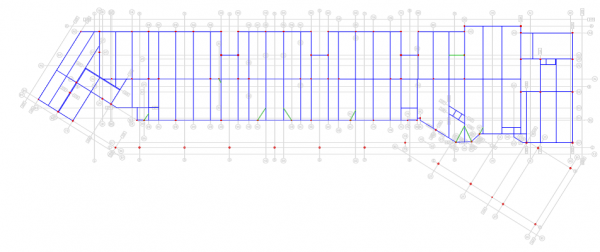
The two storey outpatients unit is approximately 75m long by 15m wide and comprises a steel frame with a 130mm deep composite steel deck for the floors. The building frame grid plan varies with maximum column spacing of 7.5m. Column sizes are typically 150mm square hollow sections and a maximum beam size of 610UKB. The layout of the first floor is shown in the figure below.

Floor vibration assessment
The floor area was modelled using 79 mm thick shell elements (i.e. the depth of the concrete above the SMD R51 profile) to represent the composite slab. The density of the material was adjusted to take account of the additional concrete in the troughs of the profile and the floor loading, and the stiffness was modified in one direction to represent the troughs of the deck. These shell elements were, in turn, connected to the nodes of the beam elements. In accordance with SCI P354[2], the dynamic Young’s modulus of the normal weight concrete was taken as 38 kN/mm2.
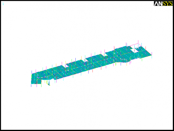
The beams were modelled using offset beam elements with rigid beam-to-column joints (although joints are designed to be pinned, for floor vibrations the strains are not large enough to overcome the friction and so pinned joints may be treated as fixed). The columns were pinned at their assumed inflexion points, located mid-height between the floors. Large voids for lift shafts and staircases were assumed to be rigid cores and so the surrounding steelwork was assumed to be fully fixed. The finite element model is presented in the figure below.

The finished floor was analysed under the permanent load (self-weight and superimposed dead load from the ceilings and services, taken to be 2.79 kN/m2 and 0.51 kN/m2 respectively) plus 10% of the imposed and partition loads (taken to be 4.0 kN/m2 and 1.0 kN/m2 respectively). The level of damping was assumed to be 3.0%, which corresponds to a fully fitted-out and furnished floor in normal use.
Current standards[3][4] describe human discomfort in terms of the perceived acceleration of the floor; floor suitability (in relation to vibration) is assessed by comparing the predicted acceleration with a set of defined acceptance criteria. Personal discomfort is recognised in the Standards[3][4] by applying multiplying factors to the acceptance criteria for different situations.
A dynamic analysis of the first floor of the New Out-Patients Unit was modelled using the ANSYS finite element software to determine the modal properties including natural frequencies modal mass and mode shapes. A modal superposition analysis was subsequently performed on the floor to determine the likely accelerations arising from walking activities based on the approach presented in section 6 in SCI Publication P354[2].
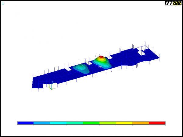

The analysis showed that the fundamental frequency of the first floor is 10.13 Hz. As this frequency is greater than 10 Hz (low to high frequency cut-off for general floor areas) it was necessary to analyse the floor for transient responses rather than for steady-state response. This transient case, considers the effects of walking as a series of impacts which occur as the walker’s heels hit the floor.
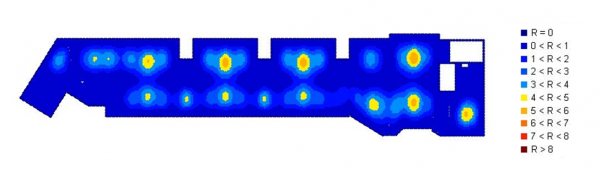

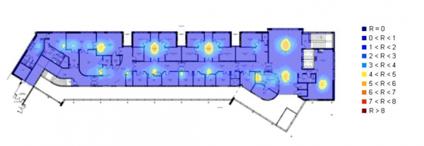
The peak response factor R for the first floor was determined to be 5.68, which is acceptable for offices and consulting rooms, are R is less than 8 (HTM 08-01)[1]. Superposition of the transient response factor contours onto the architectural floor plan showed that the response factor contours for values in excess of 4 did not ingress within the treatment room areas. Care however must be taken to identify precisely where the response factor hot spots are located as the limiting values range between <1 to <8.

The transient response of the first floor showed that the New Out-Patients Unit meets the requirements of the HTM 08-01[1] for vibrations control.
References
- ↑ 1.0 1.1 1.2 Health Technical Memorandum 08-01, Acoustics. Department of Health, 2013
- ↑ 2.0 2.1 SCI P354: Design of floors for vibration: A new approach (Revised Edition), 2009
- ↑ 3.0 3.1 ISO 10137: Bases for design of structures – Serviceability of buildings against vibration, International Organisation for Standardization, 2007.
- ↑ 4.0 4.1 BS 6472-1:2008, Guide to evaluation of human exposure to vibration in buildings. Vibration sources other than blasting, BSI.