


Thermal mass


Thermal mass is the ability of the fabric of a building to absorb and store heat. Effectively utilised as part of a whole building HVAC strategy, it can reduce the energy required for cooling and, in some buildings, remove the requirement to provide air conditioning entirely. Thermal mass can also be used to provide heating but this article deals only with cooling, and specifically in multi-storey, non-domestic buildings.
There is a common belief that heavyweight buildings are more effective than lightweight alternatives in mobilising optimum levels of thermal mass for cooling. This has probably arisen because buildings such as old churches and castles generally remain cool, even in the hottest of summers. However, the main reason that such buildings remain cool has nothing to do with their heavyweight construction. It is because they have relatively few windows, which reduces solar gain, and are usually lightly populated, which reduces internal gains.
In modern multi-storey, non-domestic buildings, the greatest accessible thermal mass is found in the concrete slabs which commonly form the upper floors. Independent research[1] has shown that the optimum thickness of concrete floor slab for providing thermal mass on a diurnal cycle of heating and cooling in the UK is 75 - 100mm. This thickness of concrete floor slab is available in almost all steel-framed buildings.
[top]Introduction

Thermal mass, more correctly called fabric energy storage, is the ability of a material to absorb and store heat. It is important in construction because, utilised effectively, it can act as a thermal flywheel, smoothing out temperature variations within a building. This can have a number of advantages, including:
- Reducing reliance on mechanical services to achieve thermal comfort
- Stabilising daily temperatures in both summer and winter, giving greater thermal comfort to the occupants
- Reducing peak loading on the HVAC plant for both the heating and cooling systems
- Reducing cooling loads in air-conditioned buildings
- Potentially reducing running costs and energy use
- Reducing the building interior volume taken up by building services
- Thermal mass can remove the requirement to provide air conditioning entirely in some buildings.
The use of thermal mass as a deliberate mechanism for controlling the internal temperature of buildings is not new. The idea was however given fresh impetus in the early 1990s in response to an increased understanding of the need for energy reduction in buildings. At that time, some Architects noticed that certain types of building, usually those that were relatively old and structurally massive, rarely overheated, even on the hottest summer days. The conclusion drawn was that this was because the large physical mass of the building absorbed excess heat. The logical corollary of this conclusion was that incorporating large amounts of high density materials which could absorb heat, i.e. concrete or blockwork, into the fabric of a building was good because it maximised the amount of cooling potential. This led to a vogue in certain quarters for large mass buildings, in some instances with non-structural elements introduced into the building for no other reason than to improve the natural cooling.
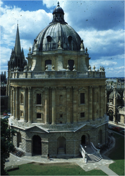
This conclusion however was inaccurate on several fronts. The reason why buildings such as the Radcliffe Camera (pictured) rarely overheat is because the overall energy balance of the building is strongly influenced by factors such as the relatively small openings and windows on the façade, which permit only slight solar gains within the building, and also because the comparatively low levels of internal activity produce only modest levels of incidental heat gain. In addition, and this was not understood until relatively recently, there is a significant physical limitation on the amount of the fabric of the building that can be utilised to absorb heat.
Nevertheless, properly employed, thermal mass has proven to be a useful tool in low energy design of buildings. These pages explain the scientific principles behind thermal mass, how to make it work most effectively, and its limitations.
[top]How it works

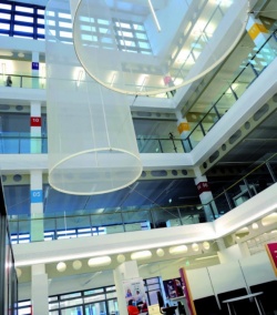
(Image courtesy of 3DReid Architects)
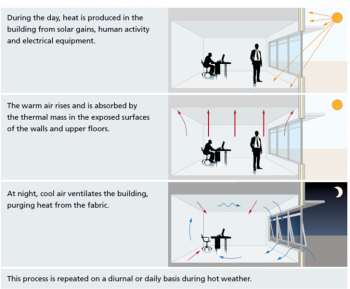
Solar gains, equipment use and human activities within buildings generate heat. When those parts of the fabric of the building which contain the greatest potential to absorb heat, most commonly the floors (via the soffit face) and, to a lesser degree, the walls (in particular, the upper portion), are exposed, the warm air flows across them and the energy is transferred between the two media. This need to expose the absorbing surfaces usually requires removal of the suspended ceiling, although perforated ceilings can be used.
This energy transfer can significantly reduce air and radiant surface temperatures. These are often combined as the dry resultant temperatures, an indication of the temperature perceived by the occupants. Most systems which utilise thermal mass are designed so that, at night, cool air is introduced to ventilate the building. This flows across surfaces which have absorbed heat during the day, purging the energy, cooling the surface and thus allowing the process to begin again the following day. The daily variation in temperature is rarely less than 5°C in the UK, making night cooling a relatively effective way of removing the heat. Alternatively, or in addition to night purging, active measures such as mechanical ventilation and water cooling may be used. Used effectively, thermal mass reduces internal temperatures and also acts to shift the time of peak temperature.
Thermal mass can also be used to provide heating in buildings, although this is less common than utilising it for cooling. This is achieved by allowing radiant heat from the sun to be absorbed through east, west and south facing windows during daylight hours. During the evening the heat is gradually released back into the open spaces, helping to maintain a comfortable temperature and reducing heating requirements.
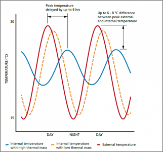
This has the impact of reducing the dry resultant temperature and delaying the peak temperature


[top]Methods for mobilising thermal mass
Systems for mobilising thermal mass are generally described as either passive or active. All of these systems can be utilised effectively in steel framed buildings.
[top]Passive thermal mass systems
Passive thermal mass systems rely on natural ventilation to disperse the heat absorbed by the upper floor slabs. As they are dependent on wind direction and speed, they are only suitable for buildings with relatively simple requirements and low cooling loads (up to 30 W/m2). They are easy to operate, with low capital, maintenance and operation costs.
Natural ventilation can be achieved from one side only, by cross ventilation or by stack ventilation, generally using atria. The control of the ventilation is fundamental to the optimum operation of passive thermal mass systems.
[top]Active thermal mass systems
In active thermal mass systems, the heat exchange with the structure is enhanced by mechanical ventilation, either within the core of the slab or over its surface. In practice, the methods used to mobilise thermal mass in the UK are usually mixed-mode systems combining natural and mechanical ventilation, with natural ventilation being the default mode to minimise energy consumption.
Common ‘active’ FES systems include:
Under floor ventilation with exposed soffits.
In this solution, the under floor void is used as a supply plenum, allowing good heat interchange with the floor slab. When used in conjunction with exposed soffits, thermal linking on both sides of the slabs is enabled.

Exposed hollowcore slabs with mechanical ventilation.
In this system, the heat exchange between the floor soffit and the occupied space is supplemented by low velocity air passage within the hollow slabs.
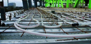
Water cooled slabs.
In this system, heat transfer is achieved by water circulating in pipes embedded within the floor slabs. Condensation is avoided by using water at between 14-20°C and therefore water from sources such as rivers, lakes, boreholes, etc, can be used. Alternatively, the water can be chilled mechanically. The system can also be used in heating mode by circulating water at between 25-40°C.
[top]Technical parameters
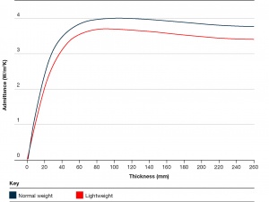

The most commonly used parameter for assessing the potential thermal mass of building materials is its admittance. BRE Digest 454, Part 1[1] defines this as: the rate at which a square metre of surface area can absorb heat from the air at a temperature difference of 1°C, expressed as units of W/m2K. In theory, some exposed surfaces, such as concrete soffits, can have admittance factors of over 20 W/m2K. In practice, the resistance to heat flow at the surface limits this to a maximum of about 8.3 W/m2K. A report from the BRE Energy Conservation Support Unit (BRECSU)[2] states that: Admittance is dependent upon a number of material variables – notably density, thermal capacity, and the thermal conductivity of the first 100 mm or so (for a 24-hour cycle) below the surface.
Admittance is a function of the depth of the material absorbing the excess heat. BRE Digest 454 Part 1[1] states that: Based on a 24 hour period..…temperature variations penetrate up to about 100mm…..depending on the material type and the rate of heat transfer. Increasing the amount of thermal mass available beyond the 100mm depth on a specific surface offers little benefit for a diurnal cycle. Summarised, this means that, on a 24 hour cycle of heating and cooling, it is possible to utilise only 100mm of mass to absorb excess heat. This is something that has been recognised for some time and has been widely reported in published papers[3][4] and which has been accepted by the steel and concrete construction sectors.
Caution is urged however against the use of admittance values alone to determine the thermal mass potential of buildings. If it is to be used to assess the operation of a complete building then it is likely to provide an answer significantly at variance with the real performance. A more accurate answer is likely to be found from the use of dynamic thermal models for the calculation of the heat transfer processes and also the use of bulk flow models to simulate the effects of variables such as air flow and turbulence.
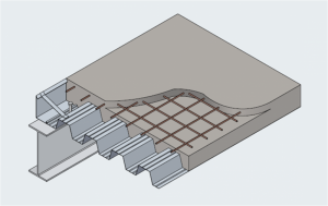

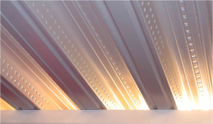
Surface finish can also have an effect on the ability of a structure to absorb excess heat. Recent work carried out by Tata Steel R&D investigated the effects of the steel deck on surface absorption. Overall, a concrete surface is about 15% better than a bright composite steel deck in terms of the ability to allow heat flow across the surface. This essentially means that, assuming a flat surface, the concrete will absorb heat at a quicker rate than the steel. Steel decks are not flat however and a typical deck has 1.4m2 of available surface area per m2 of ceiling area. This more than compensates for the greater absorption of the concrete. A dull, painted or polyester coated steel deck will perform better than one which is bright.
Most common steel and concrete flooring systems are sufficiently thick to optimise the available thermal mass in modern buildings. The most common flooring system used in the UK is composite construction using a steel deck supported by steel beams (shown). This will typically be of the order of 130-150mm thick with 70-90mm of this above the rib of the deck. Steel beams with precast planks (composite and non-composite) are also common and will typically have a floor thickness of 200-250mm. Reinforced concrete floors will typically be 250mm+ thick.
[top]Analysis
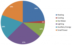
The first step in any calculation of thermal mass potential should be an analysis of the likely energy use in the building and the breakdown of that energy use. If it is intended to use the building’s thermal mass for cooling then it is necessary to demonstrate that there is sufficient cooling energy demand to justify it. The use of thermal mass has implications for building design and cost. It is not necessarily free and therefore its use must be justified. In the examples below, it would probably be considered that the energy required for cooling in the school was too small a proportion of the total to justify using thermal mass but in the office it might be considered that utilising thermal mass could be justified. (This is not a general conclusion and applies only to the specific buildings to which those energy use profiles apply).
If an energy audit demonstrates that the use of thermal mass will be cost effective then a comprehensive thermal modelling analysis may incorporate the following variables:
- The use of different g-values for the glazing. The total solar energy transmittance (TSET or g-value) is the sum of the solar energy transmittance of the glazing and the solar energy that is absorbed by the glazing, which is then re-radiated inward. It is possible that this may be more cost effective that exposing the fabric of the building to utilise the thermal mass
- Different HVAC and ventilation strategies. This is particularly important if a naturally ventilated solution is the preferred option
- Furniture mass factor. This is a method of taking account of the thermal mass of furniture and equipment within a building. For an empty space it is 1 and for an average density office it is typically about 10
- Different weather data. Any dynamic analysis should be based on real weather data. It is also advisable to analyse the building performance in light of changing weather patterns. CIBSE Test Reference Year weather data, meant to represent mean weather conditions over a period of 30 years is available. The data, adjusted to other years and weather variations, is also available
Different forms of construction may also be considered but, since it is only the first 100mm of mass which can be mobilised to absorb excess heat, and this is available in almost all steel and concrete intensive flooring systems, it makes very little difference to the overall result.
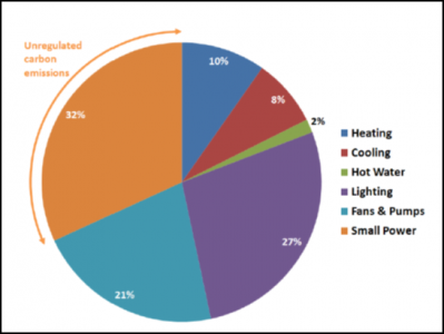
Breakdown of operational carbon emissions (by energy use) for a typical city centre office building

Breakdown of operational carbon emissions (by energy use) for a school


[top]Building studies
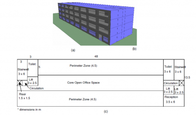

A number of building studies have been carried out to examine the amount of thermal mass that can be mobilised by functionally equivalent buildings with different flooring systems. One of these was conducted by Aecom in 2007 in which the cooling potential of various flooring solutions in a naturally ventilated, 4 storey office building was examined. It is published as Thermal mass performance in commercial office buildings.
Five floor constructions were investigated for their role in building fabric energy storage. There were no suspended ceilings so the underside of the floor slab, the soffit, was fully exposed. The key variations in floor construction with respect to the thermal mass properties are highlighted as shown.
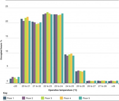
The results show that the ability to utilise thermal mass to prevent overheating was independent of the various floor constructions. This was due to the fact that all the floor constructions provided the maximum 100mm thick floor which can be mobilised.
In this instance, the results also showed that all flooring systems maintained temperatures below 28°C for more than 99% of the occupied hours. This was within CIBSE guidance[5] at the time, and so mechanical cooling would not have been necessary in this building. However, in the 2015 version of CIBSE Guide A[6] the limits have become more onerous and so now this building may well require mechanical cooling.
Two other conclusions from the study were:
- The effect of improving the solar performance of the glazing was shown to be as significant as increasing the available thermal mass in terms of reducing cooling requirements; this was based on a comparison between standard clear low-e glazing and high performance neutral solar control glazing with 40% glazing area.
- The effect of climate change based on the UKCIP medium high scenario for 2050 [UKCIP02] was modelled and this demonstrated that it would become very difficult to operate this building as naturally ventilated and still maintain acceptable comfort conditions.

| Floor construction | Modelled concrete thickness (mm) | Admittance (W/m2K) |
Decrement factor |
|---|---|---|---|
| (1) Composite flat slab – ComFlor 225 | 137 | 6.93 | 0.454 |
| (2) Composite flat slab – ComFlor 70 | 104 | 6.35 | 0.547 |
| (3) Precast concrete | 200 | 5.87 | 0.268 |
| (4) Reinforced concrete | 300 | 5.64 | 0.146 |
| (5) Hollow core precast | 200 (with circular cavities; 145mm diameter at 189mm pitch) | 5.15 | 0.398 |
[top]Limitations
Thermal mass is not a panacea for reducing the cooling energy needs in all buildings. It usually works best in buildings which can utilise natural ventilation. It is rarely used in buildings in areas of high atmospheric pollution, buildings where natural ventilation solutions would create a security risk or buildings where the cooling demands are low. Difficulties may also occur in highly compartmented buildings, due to the problems of generating a cross flow of air to cool the slab at night. This was demonstrated in the Target Zero schools project and is described in the schools design guide.
Knowsley school: the high level of compartmentation and low cooling requirement meant that attempting to mobilise thermal mass in this building would have had little value
Breakdown of operational carbon at Knowlsey School

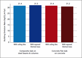
The feasibility of utilising thermal mass in large city centre office buildings was also examined in Target Zero and described in the office design guide. This work was based on One Kingdom Street, a 10-storey office building in central London. Equivalent lightweight (steel) and heavyweight (concrete) structures were modelled both with and without suspended ceilings. Despite the heavyweight structure being more than twice the mass of the lightweight structure, dynamic thermal modelling showed less than a 1% variation in the predicted annual operational carbon emissions. The modelling results showed that when the ceiling tiles were removed to expose the floor soffits, the additional thermal mass benefit was negated by the increased internal volume that required additional heating and cooling.
- Thermal mass in a large inner-city office
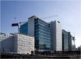
One Kingdom Street in London provided the model for an analysis of thermal mass in a large, inner-city office block
The Kingdom Street analysis showed that there was little value in mobilising thermal mass in this building


[top]Factors when considering when to use thermal mass
When considering whether to use thermal mass, important factors to consider include:
Location
Air quality, external noise and security issues, particularly in city centres, often preclude a natural ventilation strategy.
Occupancy
Thermal mass strategies are best suited to buildings with intermittent occupancy patterns such as offices and schools, which enable night cooling to take place outside normal working hours. Buildings which are permanently occupied, such as hospitals, are less suitable.
Building form
Natural cross-ventilation is only effective in narrow plan buildings. In deeper plan buildings atria can be used to provide natural ventilation. Ventilating highly compartmented buildings naturally is difficult and this can preclude effective thermal mass strategies in buildings such as hospitals, hotels and some schools.
Thermal mass should not be considered as a ‘stand alone’ solution; simply exposing the upper floor soffits in a building is unlikely to be effective. To work well, thermal mass needs to be integrated into an holistic building design which considers:
- Orientation of the building to optimise natural ventilation, day lighting and solar gains
- Fenestration – both in terms of location and area of glazing and its material properties
- Shading (both internal and external) to control and limit solar gains
- Limiting internal heat gains
- Servicing strategy – particularly the ventilation strategy.
Each building is bespoke and therefore a detailed assessment is required to establish the suitability of using and optimising a thermal mass strategy.
[top]Practical issues
Utilising thermal mass has the potential to save carbon and operational costs over the lifetime of the building. Nevertheless, as it involves exposing the upper floor soffits, there are other consequential factors that should be considered early in the design process. These include:
- The quality of the soffit finish
- The routing, co-ordination and integration of services
- The acoustic properties of the occupied space - to avoid reverberation and echo, sound-absorbing baffles suspended from the slab may be required.
These factors should be costed and weighed against the likely operational cost savings from utilising thermal mass.

The cost of preparing a concrete surface to an acceptable visual standard in particular can be significant, mainly because everyday concrete finishes are unlikely to be aesthetic. The following advice may be of value:
- An aesthetically pleasing finish requires increased care in forming and shaping the surface. Precast concrete may provide a better solution than in-situ
- Painting will overcome colour variations in the concrete but will not mask physical imperfections in the surface
- Significant care in preparation is required if an aesthetic concrete surface is to be provided with in-situ concrete. Formwork must be new and complete sections between designated construction joints must be capable of being concreted in a single operation. Also, formwork must be adequately supported to prevent differential movement
- The manner in which lights shine on the surface has an important bearing on the standard of finish which will be required. Mould joints and formwork joints will be visually emphasised, particularly if light shines across the surface at an oblique angle.
- The standard of finish must be clearly indicated on architectural drawings and defined in the specification. Ambiguity in the finish can lead to disputes later in the contract;
- High standards of dimensional tolerance in casting the slabs is required;
- Sample panels should be specified to demonstrate the standard of finish required and capable of being achieved;
- Aesthetic surfaces must be protected after preparation to retain the specified surface finish.
All of this adds time and cost and should be factored into the construction planning.
If a steel deck floor is used, the metal deck will require some cleaning after the concrete is poured. However, an aesthetic finish can be achieved by using an etch primer and then over-painting. One can also use coated deck, (i.e. a steel deck with a polyester coating) for aesthetic finishes. In addition to improving the appearance, this also improves the heat transfer and light reflection properties of the exposed ceiling, although care must be taken if this is to be used compositely as the shear studs cannot penetrate the coating.
[top]Perforated ceilings
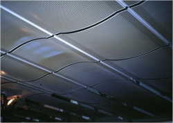

A possible solution to problems in providing an aesthetic finish to floor soffits designed to provide thermal mass is to use a permeable suspended ceiling that both allows movement of air up to the slab and hides the soffit from view. The Steel Construction Institute has worked with the Oxford Institute for Sustainable development to examine the thermal effects of different types and layouts of perforated suspended ceiling tile[7].
Test results have shown that perforated metal ceilings can still allow significant heat transfer to and from the soffit. They were found to increase the radiative effect, which compensates for the loss in convective heat transfer resulting from the perforations' flow resistance. An open area of 20% is about the maximum that can be used if a perforated ceiling is to hide the soffit. This allows approximately 40% of the convective heat transfer that would occur with an exposed slab. However, the thin metal tiles in the ceiling absorb and re-radiate heat from the air into the slab, increasing the radiative component to nearly 50% of the heat flux at the soffit surface. Under test conditions, over 85% of the cooling effect of an exposed soffit can be obtained with a thin perforated steel ceiling, at the same time as hiding the ceiling void.
[top]Prolonged high temperatures
Advocates of the theory of man-made global warming, including amongst their number the great majority of climatologists, forecast global average temperature rises of between 2°C and 6°C by the end of the century. Under these scenarios, the weather patterns in the United Kingdom will be dominated by longer, hotter summers and milder, wetter winters. Associated with this will be prolonged summer heat waves. These heat waves, characterised by hot nights, will mean that the diurnal cycle of heat storage and purging in buildings which utilise exposed mass for cooling purposes will be interrupted. In such circumstances, some commentators have advocated the use of large mass structures on the grounds that the excess heat in buildings will have the opportunity to penetrate into the fabric to far greater depths than the 100mm that is utilised by the diurnal cycle. There are a number of reasons why one should be wary of this:
- No definitive studies of the performance of heavy versus light structures during prolonged periods of heating have been carried out to substantiate the claim
- Although a large mass structure is likely to store more excess heat during a period of prolonged high temperatures, it will also require a longer period to purge it of that heat. The likely result is that heavy structures will exacerbate over-heating effects beyond the period of high temperatures.
Evidence from Australia[8] indicates that, in hot climates, heavy buildings with high levels of thermal mass may aggravate the effects of high temperatures by slowing the rate at which cooling takes place in the evenings.
[top]Claims and clarifications
A number of claims are widely made about thermal mass. The following addreses some of these:
| Details of the claim | Clarification |
|---|---|
| Only 75-100mm of concrete is required to provide optimal thermal mass in a building. | This is correct. On a 24 hour heating and cooling cycle, only 75-100mm of concrete can be mobilised to provide thermal mass. This has been accepted by the Concrete Centre, the BRE and the steel construction sector. Almost all floors, whether supported by steel or concrete frames, will provide this much concrete. |
| Used effectively, thermal mass will facilitate the use of naturally ventilated solutions for modern buildings. | For many situations this is correct. However, predicted changes to future weather patterns, with increasingly warm summers, mean that a building which will provide a naturally ventilated solution now may not do so in the future. |
| Thermal mass has the potential to significantly reduce energy requirements in all buildings. | This is not always correct. Some buildings have relatively low cooling loads, in which case trying to utilise thermal mass will offer little value. The layout and geometry of other buildings will also reduce the benefits of thermal mass; for example, heavily compartmented buildings will limit air flow and restrict the effectiveness of night time purging of the exposed slab. An audit of energy use in a building is always advisable if one is considering utilising thermal mass. Trying to force thermal mass use into a building is also an approach which is not advisable. It is very possible that this may have a negative impact on the functionality. The thermal mass might work but the compromises necessary to implement it may have such a negative effect on the building as to make it uneconomic. |
| The high thermal conductivity of steel means that a steel framing system is ineffective at storing heat. | The nature of the supporting beam in a frame is irrelevant to the thermal mass potential of a building. It is the floor which stores the heat and the floors of both steel and concrete framed buildings are constructed mainly from concrete. |
| Thermal mass is free. | Thermal mass is free in the sense that it is there to be used in almost all buildings. However, if thermal mass is to be mobilised it can lead to significant additional costs in terms of ensuring a clean aesthetic finish to the exposed surfaces. Surface preparation can take considerable additional care, which adds to construction time. |
| Structurally massive buildings can mobilise greater levels of thermal mass than lightweight buildings during a prolonged warm period. | This is a claim that is often made but never proven. It is correct to say that thick floor slabs, such as one might find in a post-tensioned slab, will soak up more heat than a thin composite metal deck floor if a prolonged period of warm weather restricts night time purging. However, this may have two negative effects. Firstly, it has the potential to create a giant thermal ‘flywheel’ within the building which will increase the radiant temperatures. Secondly, the thicker slab will take longer to cool when the weather eventually breaks thus prolonging the effects of the warm period. |
| Thick slabs can mobilise greater thermal mass if the heat is absorbed from both sides. | There is some truth in this. If a thick concrete slab is used with a raised floor and underfloor ventilation then the top part of the slab can be utilised. It should be recognised however, that this is less efficient than direct exposure of the soffit and may involve additional costs. |
[top]Case studies


[top]References
- ↑ 1.0 1.1 1.2 Braham, D. et al. Building Research Establishment Digest 454, Part 1: Thermal mass in office buildings, an introduction.
- ↑ Willis, S., Fordham, M., Bordass, B. Avoiding or minimising the use of air conditioning. Building Research Establishment Energy Conservation Support Unit, Best Practice Programme, General Information Report 31, 1995
- ↑ Cousins, F. and Lang, B. Aspects of structure and thermal mass. Seminar paper available from the Steel Construction Institute
- ↑ Barnard, Nick and Ogden, Ray. The thermal capacity of steel framed buildings. Seminar paper, July 1996, available from the Steel Construction Institute
- ↑ Guide A – Environmental Design, Chartered Institute of Building Services Engineers (CIBSE), London, 2006, p336
- ↑ Guide A – Environmental Design, Chartered Institute of Building Services Engineers (CIBSE), London, 2015
- ↑ Kendrick, C. Permeable ceilings for energy storage, Building Services Journal, August. 1999
- ↑ Sustainable building solutions-thermal mass. Technical bulletin No. 7. 22 June 2009. Published by Bluescope Steel
[top]Resources
- Environmental floor systems
- Thermal mass performance in commercial office buildings
- Steel construction – Thermal mass
Target Zero design guides:
- Guidance on the design and construction of sustainable, low carbon office buildings
- Guidance on the design and construction of sustainable, low carbon school buildings