


Twentytwo, 22 Bishopsgate, London
Article in NSC November 2018

City’s tallest tower
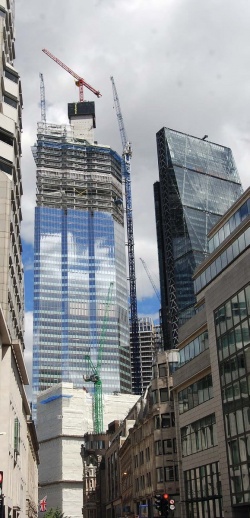
Known as Twentytwo, the City of London’s latest signature commercial building will be head and shoulders above all others in the square mile.
By Martin Cooper
Topping out at 62-storeys and 278m-tall, Twentytwo located at 22 Bishopsgate will on completion be the City of London’s highest building, and second only to the Shard in western Europe.
Being built on the plot of the previously stalled Pinnacle scheme, the new development incorporates the below-ground elements of its predecessor, including three floors of basement and a raft slab supported on piled foundations. From ground level upwards it is a steel-framed structure surrounding a large central core, with minimal internal columns ensuring long clear spans of up to 17m. Twentytwo will eventually offer an impressive 118,000m2 of flexible workspace for all sizes of businesses.
The building will be the first of its kind to house a food market, brimming with fresh tastes and open kitchens, while other amenities will include an innovation hub, gym, well-being retreat and spa, a restaurant and London’s highest free public viewing gallery.
Constructing one of Europe’s tallest structures on the site of a previous scheme was always going to throw up a few snags. “Reusing the foundations was the project’s biggest challenge,” says WSP Project Engineer Diego Padilla Philipps. “In the end, we re-used 100% of the existing piles, although some are not in the most convenient positions for the new structure.”
In order to remedy this pile position challenge, transfer structures have been introduced at basement level and level two to support columns that do not have a pile directly below them. The basement level transfer structure supports one column that extends up to the full height of the building. The transfer structure is a 15m-long plate girder weighing approximately 97t. Meanwhile, the level two transfer structure is another giant steel member that also transfers loads from perimeter columns. This plate girder weighs in excess of 100t and is 14m-long.
An existing access route to the basement loading bay necessitated steelwork contractor Severfield to design, fabricate and erect a structure dubbed the ‘Rhino’ truss because of its shape. “This is circa 150t in weight and was erected using two tower cranes. We had to get a special dispensation from the manufacturer to uprate the cranes for the erection of this truss,” explains Severfield Project Manager Kyle Fletcher. “It is made up of site bolted booms, nodes and diagonals, with the heaviest node weighing approximately 20t.”
In order to maximise the building’s floor space and help the remainder of the perimeter columns locate on existing pile positions, the structure’s lower columns, up to level 7, are mainly inclined. As the columns are raking outwards there are some large structural reactions and transfer forces. To counteract this, the floor beams are slightly larger on these levels and installed in a diagonal orientation, as opposed to being perpendicular to the core.
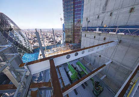
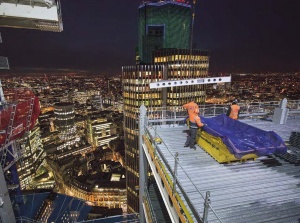
Outrigger systems have been installed on two levels
Outrigger truss positioned on Level 41


Like most UK high-rise commercial buildings, the superstructure comprises a composite design of cellular beams supporting metal decking and a concrete slab. This provides a diaphragm action restraint to the perimeter columns.
A centrally-positioned core contains 35 lifts, providing direct access from the entrance lobby to all levels. Squeezing so many lifts into one core, without intruding on any of the valuable floor space, meant a long slender core design was chosen. Consequently, the core cannot provide the necessary structural stability to the superstructure’s steel frame during high winds. This has required the installation of two giant outrigger stability systems positioned on two intermediate floors, adding some stiffness to the building and controlling sway and acceleration.
Mr Padilla Philipps uses a skiing analogy to describe the work the outriggers perform. “If a skier has his arms straight down by his sides, there is very little stability. However, by introducing poles with arms outstretched one can maximise stability.”
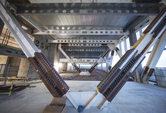
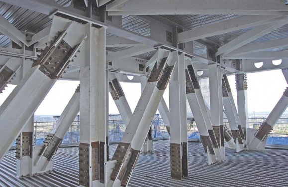
Positioned at levels 25 and 41, both of which are double-height floors containing plant equipment, the outriggers are large floor-to-ceiling V-shaped trusses that link the core to the perimeter columns and provide bracing. There are three sets of outrigger trusses on both floors, all of which extend from the building’s east elevation, through the core and then connect to the west perimeter columns.
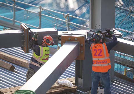
- Steel erection continues on the building’s mid levels


They were fabricated and erected in sections to form a truss. These were typically made up of a top and bottom boom, plus internal diagonals. The internal diagonals are installed with the bolts pinned in oversized holes to allow movement in the truss when the building deflects with axial shortening under gravity loads during construction. These do not become ‘active’ until the building is fully loaded, at which point they will be tightened.
The trusses vary in size depending on their locations, with the largest fully assembled truss measuring approximately 15m × 7.6m. “The booms were brought to site with complex, offset and heavy node connections on transport frames. They were designed and fabricated by ourselves to be lifted straight in to their as-built position from the back of the trailer,” says Mr Fletcher.
As there are outrigger sections embedded within the concrete core, steelwork contractor Severfield had to design, fabricate and deliver these elements well in advance of the main steelwork. Once the steelwork and floors were installed up to levels 25 and then 41, the V-shaped trusses were installed either side of the core and connected to plates left exposed from the elements inside the concrete core.
Twentytwo is due to complete by the end of 2019.
Managing windy conditions

Working on a building that will ultimately reach a height of 278m and with three tower cranes looking down on the structure from an even loftier position, it is not surprising that Severfield has had to manage the effect of high winds and gusty conditions on steel erection.
Wind is the one weather element that can occasionally delay a steel erection programme that relies on craneage, and wind speeds generally increase with height so it has more of an effect on tall buildings. However, what is surprising about this scheme is that the high winds that have occasionally suspended crane duties have mostly been encountered at low levels along the main Bishopsgate thoroughfare.
“The street is like a wind tunnel at times as gusts speed along the road between the numerous high-rise buildings,” says Severfield Senior Site Manager Micky Reilly. “This stops us picking up steel from our delivery point and lifting it up to the erectors who are working further up the building. Strangely at these times the conditions have been mostly alright for working and lifting steel on the top parts of the structure.”
To guard against such wind stoppages and mitigate any potential delays to the programme, Severfield’s erection team are working on a 24-hour basis, with a night-time shift – wind permitting – delivering and placing as much steelwork as possible in readiness for the daytime shift to erect.
Outriggers
The lateral stiffness of 22 Bishopsgate is increased in the direction of the narrow dimension of the concrete core by mobilising the perimeter columns. Richard Henderson of the SCI discusses some of the issues.
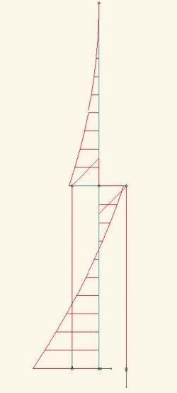

The lateral stiffness of a building with a narrow core can be increased by connecting the core to the perimeter columns by means of stiff beams known as outriggers. In 22 Bishopsgate these are provided at two levels and are double storey-height trusses. Under lateral load, the bending moment in the building core increases rapidly with distance from the top of the building. The effect of the outriggers is to apply a bending moment of the opposite sense to the core using the steel perimeter columns (see the figure).
The magnitude of the moment transferred depends on the bending stiffnesses of the core and outrigger and the axial stiffness of the columns. The intended result is that the overall stiffness of the building is increased and the maximum deflection at the top significantly reduced.
The deflection of a building is made up of the sum of shear deflection and bending deflection. The outriggers reduce the contribution of the bending deflection to the total but do not affect the shear deflection. This is because the slope of the core at the relevant level results in a vertical deflection at the ends of the outrigger which is resisted by axial forces in the perimeter columns. Under the shear deformation, the outriggers remain horizontal and no axial forces develop in the columns.
Some of these effects can be explored at concept design stage by considering the deflection of a cantilever under lateral load with a discrete moment applied at the appropriate position. For example, the maximum bending deflection δ of a vertical cantilever of height H under a uniform load with an opposing applied moment M at mid height is given by:

if W is the total lateral load on the cantilever. The perimeter columns extend and shorten by an amount equal to the deflection of the end of the outrigger. If the outrigger is at mid height and is assumed to be rigid, the building width is b and the outriggers are b/2 long, the vertical deflection of the outrigger ends can be calculated from the slope of the cantilever at mid height due to the lateral load and applied moment. The vertical deflection is given by
![]()
and is equal to FH⁄(2AEs) (either lengthening or shortening) where A is the column area. Using these expressions, the force F in the column is given by:
![]()
where m is the modular ratio. The moment and the deflection can then be estimated. A similar expression can be developed which takes account of the deflection of the outrigger.
| Architect | PLP Architecture |
| Structural Engineer | WSP |
| Steelwork Contractor | Severfield |
| Main Contractor | Multiplex |
| Main Client | AXA IM – Real Assets and Lipton Rogers Developments |