


Use of steel in cladding systems

[top]Generic forms of cladding in multi-storey buildings
Main articles: Multi-storey office buildings, Facades and interfaces, Infill walling

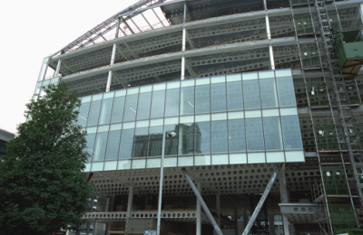
The façade systems that are used in multi storey buildings depend on the function and scale of the building. In medium to high rise city centre buildings, either fully glazed façades or lightweight curtain walling systems are generally used.
Modern curtain walling systems are ‘unitised’ and are installed in widths of 1.2 to 2.1 m and height of 3.6 to 4.2 m. An example of the use of curtain walling units in a steel framed building is shown (above right).
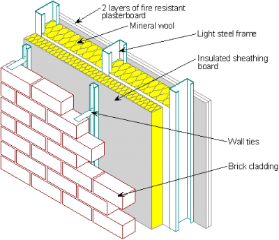
In other more conventional building types, brickwork and lightweight cladding may be connected back to light steel infill walls. A typical light steel infill wall is shown (left). In this case, the brickwork is ground supported for heights of up to 12m and is laterally supported by the infill walls.
[top]Cladding interfaces with the structure
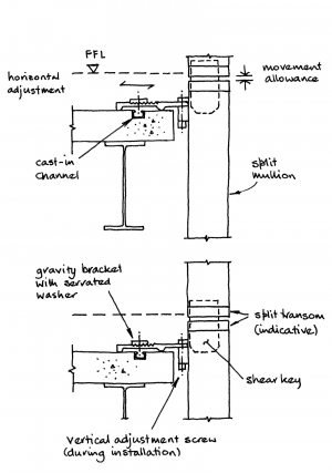

The connection of unitised curtain walling systems to the edge of a steel framed building is often made by specific connection systems that attach to the top of the slab and are contained within the raised access floor. An sketch of this type of system is shown right. These attachments allow for adjustment on site to allow for variations in the deflection of the beams and site tolerances.
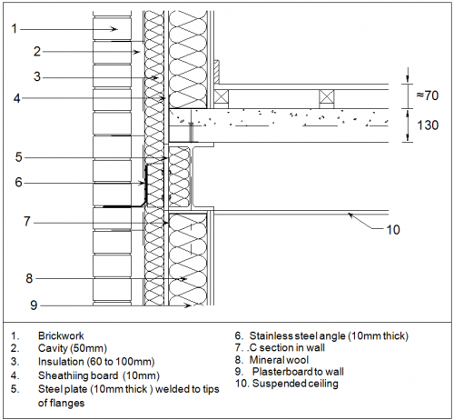
Brickwork may be supported at each floor by the edge beams in steel frames. These attachments are in the form of stainless steel brackets that are connected to steel plates welded to the edge beams. The brackets are placed at 400 or 600mm spacing along the edge beam, depending on the wall height of 2.8 to 4m (and hence its weight), and allow for adjustments on site to align with the brick coursing. The projecting stainless steel angle fits into the mortar joint. The detail shows the typical build-up of materials at an edge beam to achieve a high level of thermal insulation.

[top]Glazing systems
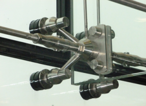

Modern glazing systems present a range of opportunities for architectural expression. They are often used in tall glazed walls in entrance areas and in atria. The generic forms of attachment are by ‘spiders’ that connect to the corners of 2 or 4 glass panes, and provide sufficient articulation at these points. A good example is shown. The supporting structure typically comprises one of the following forms:
- Posts or beams that are usually in the form of circular hollow sections (CHS), or in some cases, rectangular hollow sections (RHS).
- Vertical or horizontal trusses using smaller CHS sections.
- Inclined arms from the internal structure, where the glazing system is used to create a large atrium or featured entrance area
- Combined post and tension tie systems using:
- Single tie systems which are efficient for roofs or when positive wind pressure exceeds negative pressure as the ties only act in tension.
- Double tie systems, which are often used when the ties on one side are outside of the building, and both sets of ties act in tension. The vertical member can be very small.
[top]External features
[top]Balconies and canopies

(Image courtesy of Feilden Clegg Bradley architects)
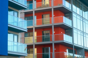
External features may include balconies or other attachments which are connected to stiff posts, such as columns, floors or beams. Balconies take various generic forms:
- Ground supported structures, which are often used for external access.
- Cantilever structures that are welded or bolted to the perimeter steel members.
- Suspended balconies from the floor above or, in some cases, from projecting beams at roof level.
An example of a self-supporting steel balcony system is shown. The use of steel beams that pass through the façade requires special provisions to control thermal bridging. Self-supporting balconies that are tied to the structure at relatively few points at the floor levels lead to minimal thermal bridges, whereas cantilever balconies require larger and more robust structural connections with proprietary thermal ‘breaks’.
[top]Solar shading
Many steel buildings are designed with external solar shading that consists either of projecting steel members or a separate external steel structure. Often these members are made from hollow sections in order to minimise their size.
Various generic forms of solar shading exist, depending on the orientation of the façade:
- Horizontal ‘louvres’ placed above and within the window depth on south facing facades.
- Vertical shading on east or west facing facades that extends over the full window height.
- Semi translucent materials such as perforated stainless steel sheets or woven wires.
The louvres may be in the form of ‘lens’ shape using oval shaped hollow sections, or circular sections with a metallic facia to form the required shape.
Some examples of the use of steel in solar shading are shown. Often, where an external steel solar shading system is used, it is combined with access for window cleaning, etc.

External steel structure for solar shading, Woking

Use of woven stainless steel as solar shading, London


[top]Cladding systems in single storey buildings
Main articles: Single storey industrial buildings, Building envelopes
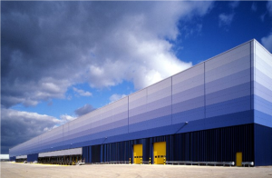

In single storey buildings, the cladding and roofing systems are generally metallic and take two generic forms:
- Built up systems, incorporating a liner tray, a separating element, insulation and the external sheeting.
- Composite panels (often called sandwich panels) that are directly fixed to the purlins or side rails.
In wall cladding applications, deep composite panels may be designed to span horizontally between the columns thereby eliminating the need for side rails.
Double skin or built up roof systems usually use a steel liner tray that is fastened to the purlins, followed by a spacing system (such as a plastic ferrule and spacer or rail and bracket spacer), insulation and the profiled sheeting.

Double skin built-up roof cladding using rail and bracket system

Standing seam panels with liner trays


As insulation depths have increased, to meet improved thermal performance standards, the ‘rail and bracket’ solutions provide greater lateral restraint to the purlins. The liner trays are used to form an airtight boundary by sealing the joints. Alternatively, an impermeable membrane may be placed on top of the liner tray.
Standing seam sheeting has concealed fixings and can be fixed in lengths of up to 30 m. The advantages are that there are no penetrations directly through the sheeting that could lead to water leakage. The fastenings are in the form of clips that hold the sheeting down but allow it to move longitudinally. The disadvantage of this system is that less restraint is provided to the purlins than with a conventionally fixed system.
Composite or sandwich panels are increasingly used as they are prefabricated elements that are produced in a range of thicknesses up to 120 mm. In roofing applications, the main fixings to the purlins are generally made through the trough of the roof profile.
[top]Further reading
- Steel Buildings, BCSA No. 35/03, Chapter 4, Single Storey Buildings
- Steel Designers' Manual 7th Edition. Editors B Davison & G W Owens. The Steel Construction Institute 2012, Chapter 5, Multi-Storey Buildings
- Architectural Design in Steel – Trebilcock P and Lawson R M published by Spon, 2004
[top]Resources
- SCI P101 Interfaces - Steel Supported Glazing Systems SCI
- SCI P167 Architectural Teaching Resource Studio Guide, 2000
- SCI P372 Acoustic Detailing for Steel Construction
- SCI P402 Light steel framing in residential construction: Chapter 10 External wall systems
- Best Practice in Steel Construction: Commercial Buildings
- Steel Buildings in Europe - Multi-storey buildings:
- Steel Buildings in Europe - Single storey buildings: