


Vision Tameside Phase Two, Ashton-under-Lyne
Article in NSC June 2017

Steel stars in town centre regeneration
Cost and flexibility played significant roles in the choice of framing material for the latest phase of Ashton-under-Lyne’s central redevelopment programme.
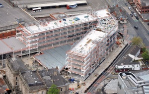
Big changes are afoot in Ashton-under- Lyne as the local authority seeks to radically improve the town centre. A central element of these plans is known as Vision Tameside and Phase Two, which consists of a new Joint Public Service Centre and Advanced Skills Centre, is currently under way.
Phase One consisted of a new building for Tameside College, which opened in 2015 and is located across the road from this second phase. As well as housing new council headquarters and other public sector organisations, Phase Two will also include a college wing, a public library, a Wilko store and an elevated landscaped public realm. Both phases will benefit from a new nearby public transport interchange which will shortly get under way. This development will help and encourage more people to travel to and from the town to access jobs, learning and leisure – three things that Vision Tameside will provide.
Being built on the site of the former Tameside Administrative Centre (TAC), which was demolished last year, the Phase Two building has been designed as one large steel-framed development, albeit one that the Council will share with other tenants.
Explaining the reasons why the Council chose to build a new centre, Councillor Jim Fitzpatrick (Executive Member with responsibility for Investment and Development) says: “The deteriorating condition of the old TAC complex, which was built 35 years ago, meant it was increasingly expensive to operate. It would have cost around £4M to bring it up to standard, and it had become far too big for the number of staff now employed. “It was simply not fit-for-purpose in the context of modern working practices and council service delivery. The new centre, which the Council will share with Tameside College, will be much cheaper to maintain as it is a modern building.”
It consists of two five-storey wings that splay outwards in a V-shape on plan. The central space is infilled by a single storey Wilko store, the roof of which will form the landscaped public realm. The realm will be accessible from the first floor of each wing and via a main staircase located to the front of the building. The architectural vision for the realm is to open up the site and form an extension of the nearby Market Place.

One of the building’s wings will be solely occupied by the Council and other public sector organisations, while the other will accommodate Tameside College’s vocational campus. The ground and first floor levels will both house public facilities. For the College this means hair salons, a bakery, a bistro and a café, while in the Council wing it will include a job centre and customer service centre. One end of the Council wing will also include a new public library which incorporates a retained façade of the former Victorian Water Board building.
Both of the wings are approximately 100m-long and are of similar structural arrangement. They are based on a column space planning grid of 7.2m × 7.3m to best suit the architectural window module size and the width of the building wings respectively. This regular column spacing is also replicated in the centrally positioned Wilko store. “The wings have been designed as one large development, albeit with a bespoke classroom fit-out for the College side,” explains Ryder Architecture Director Mark Clasper. “Although steel was chosen primarily for its cost and speed of programme, flexibility was also a prime consideration. In the future, the College wing could easily be reconfigured into a modern office due to the column layout.”
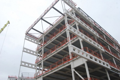
The lateral stability of the building, as a whole, is provided by the use of a braced steel frame. The building is braced in each orthogonal direction, utilising the composite floor slabs at each floor level of the building as horizontal diaphragm elements to transfer the laterally applied wind and stability forces to discrete vertical braced bays. These braced bays then transfer the applied lateral forces to the building’s piled foundations through an arrangement of continuous steel diagonal bracing members located within the main column and floor beam frames.

What is already in the ground from the demolished TAC building also played a role in the choice of a steel-framed solution for Phase Two. The demolition specification for the original Council office building required the pile elements of the building’s foundations to be left in the ground. This requirement meant that the construction of the foundations to the new building needed to be set out around these existing piles, while also providing the necessary support to the new building superstructure and its proposed column positions.
Consequently, a composite steel frame building was adopted to minimise the weight of the superstructure and to enable the new foundations to be offset around the existing piles in an economical solution. “A composite steel frame building offers a lighter frame solution than a comparable reinforced concrete frame, offering economies in the foundation design, while the use of composite floor slabs within the steel frame avoids the use of traditional formwork associated with RC frames, offering a faster form of construction,” says TPS Associate Director Andrew Forshaw.
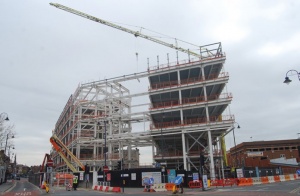
New piles were installed to a depth of 20m and, to keep the construction programme on schedule, the installation of pile caps and then the steel erection were started before the piling had been completed. This meant, that at one point, all of these trades were on-site at the same time, following each other in a sequential manner. Steelwork was erected by Elland Steel Structures in six phases, working around the project clockwise and then finishing with the central element.
The composite floors above the store area are subject to higher loads than the individual building wings to suit the build-up of finishes forming the podium deck to the elevated public realm area and its associated occupancy loads. To accommodate this design feature slightly larger steel sections were used for the store.
Vision Tameside Phase Two is scheduled for completion in early 2018.
Vierendeel Truss Design
By David Brown, SCI

A recent theme in NSC has been the design of trusses – which also feature in the Vision Tameside project. At the ends of the 100 m wings, each façade is extended as a cantilever from the main structure. Wind loading on the [Facades_and_interfaces|façade]] extensions causes out-of-plane (horizontal) bending of the cantilevers, so the vertical orientation of the trusses is a little deceptive. Vertically, the trusses carry the façade loading.
In the vertical direction, the trusses are Vierendeel trusses. Named after the inventor – Arthur Vierendeel – these trusses have no diagonal members. The classification as a truss is rather deceptive, as they are really continuous frames with moment resisting connections between the vertical members and the chords. The bending moments in the truss members are at a maximum near the supports, so in a simply supported Vierendeel truss it would not be unusual to have larger members towards the supports, possibly diminishing in size towards the centre of the span. With a cantilever Vierendeel truss, the bending moments tend to be larger at the central support.
Compared to Pratt or Warren trusses, a Vierendeel truss will probably have more expensive connections (as they are moment resisting), but has the advantage of no diagonal members - so storey-height Vierendeel trusses are sometimes used as transfer trusses within buildings, as access through the truss is maintained.
Vierendeel trusses can be analysed “by hand” – a pin is assumed at the mid-point of the members and an approximate analysis completed. The method is described and an example presented in older editions of the Steel Designers Manual (SDM). Most designers will simply use software to readily determine forces, moments and deflections, which is the method encouraged by more recent editions of the SDM.
With all trusses, the design of the joints is key, with the objective to remove the need for local reinforcement, which would be expensive. This is particularly so with Vierendeel trusses, where the bending moments must be transferred across the joints. Joint resistances can be checked using the guidance in BS EN 1993-1-8[1], with free software available from Tata Steel. It is highly likely that an iterative process of checking joint resistances, revising member sizes and re-analysis will be needed to reach an optimum solution, both structurally and economically. This best practice iterative approach was followed for the Vierendeel trusses in the Vision Tameside project – although like so much elegant engineering, the trusses will be concealed by the cladding in the completed structure.
| Architect | Ryder Architecture |
| Structural Engineer | TPS |
| Steelwork Contractor | Elland Steel Structures |
| Main Contractor | Carillion |
| Main Client | Tameside Metropolitan Borough Council |
References
- ↑ BS EN 1993-1-8:2005. Eurocode 3: Design of steel structures. Design of joints, BSI