


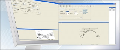
Modelling and analysis
Structural analysis is the process of calculating the forces, moments and deflections to which the members in a structure are to be subjected. There is a vast range of analysis tools offering speed, precision and economy of design; 3-D, FE modelling, bespoke portal frame, cellular beam or plate girder design software are now widely available. Modelling catenary actions, cold formed member performance or grillage analysis - all these are now commonplace for structures, where hand analysis is impossible. Increasingly sophisticated analysis methods continue to improve the accuracy with which the behaviour of structures can be predicted.
Modelling the real world behaviour of a structure is made easier by the use of full model generating software, with load generating tools enabling frame stability verification along with member checks. The design can be performed to British or European Standards.
This article explains the basics of common structural modelling approaches and describes the differences between various types of analysis. Emphasis is placed on the verification of models and analysis results to ensure a safe and economic structure is obtained at the end of the design process.
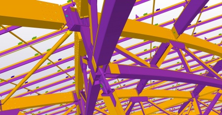

(Image courtesy of Trimble Solutions (UK) Ltd.)
[top]Understanding structural behaviour

It is recognised that with the universal presence of computer analysis, an intuitive understanding becomes increasingly important, both in the creation of analysis models and critically, in the appraisal of the analysis results, such as the deflected shape, distribution of moments or distribution of reactions.
Numerical analysis of structures relies on the designer's understanding of structural behaviour, choice of appropriate software, method of analysis and above all the use of engineering judgement to know when the answers are reasonable.
An intuitive approach uses broader, more dynamic reasoning skills to evaluate the behaviour of any particular structure. The key principles involved in developing this kind of understanding of structural behaviour are:
- To consider the deformed shape of a structure
- To use statically determinate simple systems, so that good appreciation of the behaviour of the real structure with all its complexities can be gained.
It is helpful to use the graphic options of the software to review input data, such as loads, and output data, such as deflections and bending moments.
Most orthodox buildings are a series of repeating 2-D frames and often it is convenient to model in this way. Most steel sections are highly efficient in one primary direction and moment resisting connections to the minor axis can be difficult and expensive.
However, many multi-storey buildings are modelled in 3-D, as it is very effective to copy and repeat similar floors together with defined load patterns. 3-D modelling is also useful for analysing complex frames and for cataloguing member size, type, location, etc. within the whole building model.
Braced structures with nominally pinned connections, are most cost effective. Analysis can accommodate continuous design, but the connections are more expensive.
[top]Modelling
It is generally convenient to consider first the form of the building frame in orthogonal directions, and to identify:
- The primary structural elements which form the main frames and transfer both horizontal and vertical load to the foundations
- The secondary structural elements, such as secondary beams or purlins, which transfer the loads to the primary structural elements
- The other elements, such as cladding or partitions, which only transfer loads to the primary or secondary structural elements.
At the same time, any constraints on the form of the building must be identified as these may well dictate how the structure is modelled, and in particular, which (if any) frames may be braced, and which must be modelled as rigid.
The objective for the designer is (within the constraints of the specification and any architectural requirements) to provide a safe, economical structure. The definition of an economical structure is not straightforward, and it may be necessary to investigate several forms of framing before undertaking the detailed analysis and design. However, it is possible to provide general guidance based mainly on the understanding that moment resisting connections are more expensive than nominally pinned connections. Thus in order of preference, the designer should consider:
- 'Simple' construction - i.e. braced frames with nominally pinned joints
- Rigid frames in one direction, with ties and bracing in the other
- Rigid frames in two directions.
When modelling continuous frames in three dimensions, judicious introduction of member releases is important to simplify the connection details. Without releases, joints may be subject to minor axis moments and torsions, leading to expensive details. Although software may offer the facility to introduce spring stiffness for selected directions and rotations at joints, the physical connection may be difficult or impossible to detail to meet complex performance requirements.
It must be emphasised that, in most cases, there is more than one option for the form of the building frame. Further advice on structural form can be found in the Steel Designers' Manual.
[top]Multi-storey buildings
Steel frame multi-storey structures in the UK are typically analysed and designed for two types of loading - gravity and lateral. For a structure where floor grids repeat, greater levels of repeatability within the structure, and thus a more economic design, can be achieved by analysing the structure in the following order:
1. Analyse and design the structure to resist gravity actions (self-weight, imposed actions, snow loads, etc). This structure comprises floors, often composite floor decks acting compositely or non-compositely with steel beams and columns. It is recommended to model:
(i) One typical floor first - ensuring reasonably common member sizes are used where possible to maximize standardization, whilst not wasting material unnecessarily.
(ii) Using this floor, replicate it within the building as many times as possible; design all floors and the columns for gravity combination of actions.
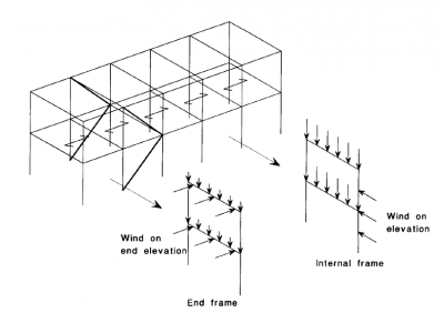
2. Analyse and design for lateral actions (arising from wind and initial imperfections etc.) and design the lateral load resisting system. This system can consist of one or more of the following:
- Braced frames - with bays containing diagonal braces or cross-bracing which resist the lateral loading in tension and/or compression
- Continuous frames with bays resisting lateral load due to frame action and moment-resisting connections between beams and columns
- Concrete shear walls which are typically planar elements or groups of planar elements (cores) which resist the lateral load in shear or shear and bending respectively.

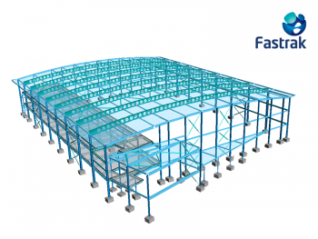
(Image courtesy of Trimble Solutions (UK) Ltd.)
A number of simplifying assumptions are made when modelling the building for analysis:
- Analysis elements are aligned with the tops of steel beams in floors thereby ignoring the small offsets in centre line between beams of different depth
- The horizontal offset of edge beams is usually small enough to be ignored
- All columns are typically modelled as being co-linear along their centre line
- small offsets of columns from grids are typically ignored in design
- to ensure that all the lateral loading is carried by the braced or moment frames (continuous framing), it is typical to assume that all columns not in braced bays or moment frames are pinned at each floor level, so they do not attract lateral loads.
More information on modelling multi-storey buildings can be found in the Steel Designers' Manual.
[top]Trusses and lattice girders
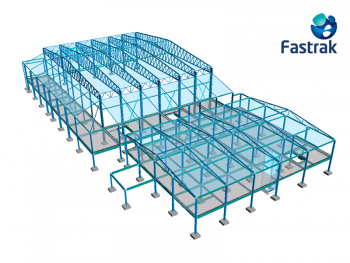

(Fastrak model courtesy of Trimble)
There are a variety of models which may be used for the analysis of a truss. These include:
- Pin jointed frames
- Continuous chords and pin jointed internal, i.e. web, members
- Rigid frames.
The first two options are preferred since in most situations there will be no bending moments to be included in the joint capacity checks and connection design. Pin jointed frames are the traditional choice to model trusses, while the assumption of continuous chords and pin jointed internals usually better reflects the behaviour in practice. In this case the chords resist some bending due to loading between nodes but behave primarily as an axially loaded continuous beam. The internals are axially loaded only - moments due to self-weight are usually ignored. The analysis model should reflect this behaviour.
In trusses using hollow sections the joints between members are generally assumed to be pinned in the analysis model, despite the fact that the internals are fully welded to the chords. This is due to the relatively thin walls of hollow sections and the large deformations that such connections can sustain.
The third option is usually only relevant to Vierendeel trusses. In this case the truss resists loads through bending action in both the chords and internals. This has the advantage that the diagonal internals are omitted but the efficacy of the hollow section is somewhat lost as the Virendeel truss acts as a continuous frame and significant moments develop at the ends of members. The connections between the hollow sections have to be stiffer since they are rigid and have to be designed to resist the bending moments.
[top]Portal frames
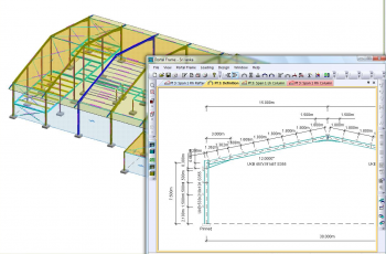

Fastrak model courtesy of Trimble
Proprietary software dedicated to the analysis of portal frames generally involves an elastic analysis to check frame deflection at the serviceability limit state, and an elastic-plastic analysis to determine the forces and moments in the frame at the ultimate limit state. These methods have largely replaced the rigid-plastic method which is unable to account for the important second-order effects in portal frames. Nevertheless the rigid-plastic method continues to be allowed by BS EN 1993-1-1[1] Cl 5.4.3 (1) providing certain criteria are met - see Cl 5.2.1(3) of the same standard - that ensure second-order effects can safely be disregarded.
BS EN 1993-1-1[1] provides three alternatives for 'plastic global analysis':
- Elastic-plastic analysis with plastic hinges (referred to below as the 'elastic-plastic method')
- Non-linear plastic analysis considering the partial plastification of members in plastic zones. This method is not generally used in commercial portal frame design
- Rigid plastic analysis neglecting the elastic behaviour between hinges.
The approach to analysis in BS EN 1993-1-1[1] is to presuppose that second-order effects need to be allowed for in the design except under special circumstances when the second-order effects are small enough to be ignored.
Haunches are frequently provided at the eaves and apex connections of a portal frame. Typical general analysis software does not have the facility to use a 'tapered element'. In such cases it is recommended to model tapered members as a series of uniform prismatic elements. The assumption that the neutral axis remains at the centre line of the rafter and does not descend towards the haunch is safe, since it tends to overestimate both the compression in the bottom flange, and the shear.


[top]Special members
Normal frame members are generally modelled as one (or more) straight elements, with associated section properties. Universal beams, universal columns, tees, angles, channels and hollow sections are modelled on this basis. Non-standard sections may require a different approach. General analysis software usually allows the creation of bespoke members by defining the section properties. For elastic analysis this includes the second moment of area about both axes, the gross area and the shear area. The shear area will be important if the analysis includes shear deflection. For three dimensional frames, the torsional moment of inertia will be required. Some software will calculate these properties based on dimensions input for standard profiles, whilst for other software the properties must be input.
[top]Curved members
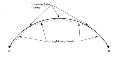

Curved members are modelled as a series of short, straight elements. Modelling by using more, shorter elements, improves the accuracy of the results. As a general guide, a length of arc corresponding to 15° produces reasonable results. More information can be found in Design of Curved Steel (SCI P281).
[top]Tapered members
Tapered members can be simply modelled as a series of short elements, each with an inertia corresponding to the depth of the member at that position. Generally, three such sections give reasonable accuracy when modelling tapered members.
[top]Castellated and cellular members

Many steelwork analysis programs provide libraries of standard section properties, and may also include the section properties for castellated beams. This will allow the structural designer to include castellated members in a frame model in the same way as standard sections. Whilst the frame bending moments produced by this approach will generally be satisfactory, the structural designer should note that the deflection of a castellated or cellular beam will be more than that predicted by Engineer's bending theory. This is due to the Vierendeel effect and to shear deflection.
As a rule of thumb, the deflection of a cellular or castellated beam may be taken as 25% greater than the equivalent depth beam without openings. Additional deflection due to the Vierendeel effect becomes more significant with multiple, long openings. As a rule of thumb, the deflection of a beam with multiple, long openings may be taken as 35% greater than that of the equivalent depth beam without openings.
In some circumstances, the structural designer may conclude that the additional deflection may be ignored, or is not critical. Alternatively an allowance may be made for the additional deflection during design and checking of the members.
More information can be found in Design of composite and non-composite cellular beams (SCI P100). Information on the deflection of composite beams with web openings can be found in SCI P355
[top]Joints
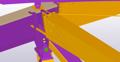

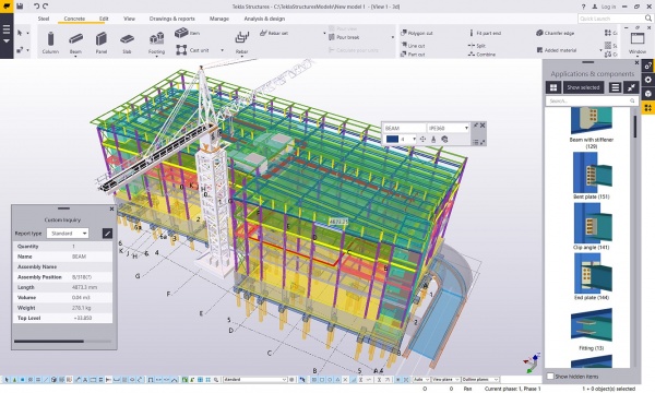
(Image courtesy of Trimble Solutions (UK) Ltd.)
Within a frame, joint behaviour affects the distribution of internal forces and moments and the overall deformation of the structure. In many cases the effect of modelling a continuous joint as fully rigid, or a simple joint as perfectly pinned, compared to modelling the real behaviour, is sufficiently small to be neglected.
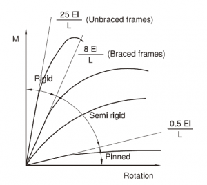

Elastic analysis programs consider only the stiffness of the joint and it is convenient to define three types as follows:
- Nominally pinned - a joint which may be assumed not to transmit bending moments. Sometimes referred to as a pinned connection, it must also be sufficiently flexible to be regarded as a pin for analysis purposes.
- Continuous or rigid - a joint which is stiff enough for the effect of its flexibility on the frame bending moment diagram to be neglected. A continuous joint must have appropriate stiffness, in addition to its moment resistance.
- Semi-continuous - a joint which is too flexible to qualify as continuous, but is not a pin. The behaviour of this type of joint must be taken into account in the frame analysis.
BS EN 1993-1-8[2] requires that joints be classified according to their stiffness for analysis and should also have sufficient strength to transmit the forces and moments acting at the joint that result from the analysis.
When classifying the stiffness of a joint:
Simple joints - are described as 'nominally pinned' rather than pinned since it is accepted that some moment is transferred. In this definition these moments are insufficient to adversely affect the member design. The UK National Annex BS EN 1993-1-8[3] indicates that connections designed in accordance with the principles given in SCI P358 may be classified as nominally pinned.
Continuous joints - are described as 'rigid joints'. The UK National Annex[3] refers the designer to SCI P398 in which, for many cases, connections designed for strength alone can be considered as rigid, if requirements described in P398 are satisfied.
Semi-continuous joints - are 'semi-rigid' and are usually also 'partial strength'. These are described as 'ductile connections' in UK practice and are used in plastically designed semi-continuous frames. For braced semi-continuous frames, the UK NA[3] indicates that these may be designed using the principles given in SCI P183 .
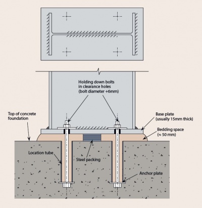
[top]Supports
The interaction between the foundation and supporting ground is complex. Detailed modelling of the soil-structure relationship is probably too involved for general analysis. Base connections fall into the same categories of nominally pinned, semi rigid and rigid as other joints, as BS EN 1993-1-8[2] has no specific recommendations covering their rotational stiffness.
More information can be found in SN045.
[top]Pinned and rocker bases
Where a true pin or rocker is used, the rotational stiffness is zero. The use of such bases is rarely justified in practice, as careful consideration needs to be given to the issues connected with shear transfer to the foundation and temporary stability of the column during erection.
[top]Nominally pinned bases
If a column base is nominally pinned and the foundation design assumes the base moment is zero, it is recommended that:
- When using elastic global analysis to establish the design forces and moments at the Ultimate Limit State the base should be assumed to be pinned.
- When checking frame stability i.e. when checking whether the frame is susceptible to second-order effects the base may be assumed to have a stiffness equal to 10% of the column stiffness (which can be taken as 4EI/L)
- When calculating deflections at the Serviceability Limit State the base may be assumed to have stiffness equal to 20% of the column stiffness.

[top]Nominally rigid bases
If a column is rigidly connected to a suitable foundation, the following recommendations should be adopted:
- The stiffness of the base should be limited to the stiffness of the column when using elastic global analysis to establish the design forces and moments at the Ultimate Limit State
- The base may be assumed to be rigid when calculating deflections at the Serviceability Limit State
- For elastic-plastic global analysis, the assumed stiffness of the base must be consistent with the assumed moment capacity of the base but should not exceed the stiffness of the column. Any base moment capacity between zero and the plastic moment of resistance of the column may be assumed, provided that the foundation and base plate are designed to resist a moment equal to the assumed moment capacity, together with the forces obtained from the analysis.
[top]Semi-rigid bases
A base stiffness of up to 20% of the column stiffness may be assumed in elastic global analysis, provided that the foundation is designed for the moments and forces obtained from this analysis.
[top]Modelling base stiffness
Bespoke software normally has the facility to select the recommended values of base stiffness. Unless such software is used, the base stiffness may be modelled by the use of a spring stiffness or dummy members at the column base.
When assessing the sensitivity of the frame to second-order effects (calculating αcr ) a nominally pinned base can be modelled with a spring stiffness equal to 0.4EIcol/Lcol. When calculating frame deflections at the serviceability limit state a nominally pinned base can be modelled with a spring stiffness equal to 0.8EIcol/Lcol.
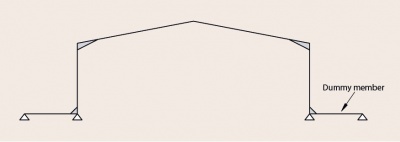

If the computer program cannot accommodate a rotational spring, the base fixity may be modelled by a dummy member of equivalent stiffness as shown below.
When modelling a nominally pinned base the second moment of area (Iy) of the dummy member should be taken as:
- Iy = 0.1 Iy,col when assessing frame stability
- Iy = 0.2 Iy,col when calculating deflections at SLS.
In both cases, the length of the dummy member is L = 0.75 Lcol, and modelled with a pinned support at the extreme end.
When using dummy members to model base fixity, the vertical base reaction should be taken as the axial force in the column.
[top]Model verification
The most important part in any analysis exercise is to review the output in order to confirm that an appropriate structural model has been used, and that the applied loads are correct. This is not to confirm that the execution of the analysis is correct! When using proven software the analysis will be correct - the exercise is to check the structural designer's input.
Software frequently contains default values for certain input data. Support fixity and restraint conditions are common examples of data which may have default values. Default values are intended to avoid the necessity for the structural engineer to enter data, and represent the 'usual' condition, which may be amended by the user. The structural designer must give due regard to the default values assumed by the program, and either decide that these are appropriate, or amend the value accordingly. All input data, whether default or user input, remains the responsibility of the designer. Default values are common in both analysis and design software.
Questions the designer should ask when reviewing the output from structural modelling software include:
| Program Defaults | Are these correct? Are the default conditions appropriate for the physical details and the loading of the frame? |
| Loading | Viewed graphically, do the loads in each loadcase appear correct? Are any elements without load?
Do loads on some elements appear to be orders of magnitude different from others? Are the loads applied in the correct orientation? |
| Deflected Form | Is the deflected form correct? Has the structure deflected as expected, and is the order of the overall deflection as expected? |
| Bending Moment Diagram | Is the form of the bending moment diagram as expected? Are moments shown where releases would have been appropriate? Does the overall envelope on a member equate to that calculated by a simplistic approach, typically wL²/8 or WL/4? |
| Reactions | Checking by hand calculation, do the total reactions provided in the output (vertically and horizontally) equate to the applied loads? Do the reactions quoted for different unfactored loadcases differ by orders of magnitude? Is the distribution of load to the supports as expected? |
| Spring Stiffnesses | Are the spring stiffness values assumed for analysis appropriate to the members as designed? |
| Trusses | If the truss is simply supported and carrying a uniformly distributed load, do the maximum chord forces equate to wL²/8 , divided by the depth of the truss?
Does the vertical component of the end internal member equate to the vertical end reaction? Are the displacements of the correct form and order? In the analysis model, is one end of the truss free to move longitudinally? Do redundant members at the ends of the truss (if included in the model) attract load, or have they been released? |
[top]Analysis of a structure
For common building structures, analysis is concerned with determining the building displacements together with the internal forces and moments that result from the applied loading. The results are determined by mathematically combining the structural stiffness of the analysis model together with the actions applied.
[top]Assumed simplifications
The analytical model of the structure is usually created by defining the idealised geometry, material properties and the structural supports. Assuming perfectly straight members is common, however this is not always the case. Next, the load model is created defining the location, magnitudes and directions of actions on the structure. These actions are typically grouped into design situations by type, e.g. permanent, variable, wind and snow, etc. Finally, combinations of actions are created which add together the actions in the design situations multiplying them by relevant factors as defined in design standards.
When the material properties are non-linear, for tension only elements or compression only supports, a 'non linear' analysis is required. Similarly, should the loads be other than static loads, for example time-dependant loading from a machine or an acceleration spectrum to model an earthquake, then a time history or a response spectrum analysis will be required.
As well as common modelling idealisations such as assuming perfectly elastic material, straight members, consistent section properties, actions applied at one point or uniformly distributed, there are also analysis idealisations and simplifications.
To determine the internal forces and moments in a building frame the following should be taken into account (if significant):
- Second-order P-Δ effects - effects of deformed geometry, that introduce additional forces caused by deformation of the frame
- Second-order P-δ effects - effects of deformed geometry, that introduce additional forces caused by deformation of the member
- Global imperfections in the structure - e.g. the 'lean' of out-of-plumb columns
- Local imperfections in members - e.g. initial bow of the member
- Residual stresses in members
- Flexural, shear and axial deformations
- Joint behaviour.
[top]Analysis by hand
The calculations required to obtain the shear forces and bending moments in simply-supported beams form the basis of many other calculations. Generally only the simplest analysis is undertaken by hand - software is pervasive.
There is no need to use software when designing simple columns or beams. Hand calculations are also useful for initial sizing of frames or continuous beams. Details regarding hand calculations can be found in many textbooks.
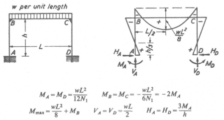

Useful formulae for bending moments, shear and deflection are presented in The Steel Designer's Manual, Appendix: Design theory or in Steel Buildings .
[top]Analysis by software

There are many analysis packages currently available on the market. They offer a wide range of features and analysis capabilities. The majority of analysis programs performs elastic analysis, but some also offer plastic or elastic-plastic analysis.
Analysis software is applicable to a wide range of structural forms: buildings, bridges, towers, masts, tented structures, etc. Some programs include the facility for different structure types, such as trusses , where the nodes are all pinned or portal frames, which allow the modelling of eaves haunches and restraint positions with ease. Usually, the engineer has to define structure geometry, member sizes, supports and actions before the analysis can be run.
The modern trend is moving towards the analysis being a subset of 'design software'. A user builds a 'physical model' in the design software defining the members and connections, the software selects initial sizes for members based on engineering rules of thumb and then creates an analysis model automatically.
Many analysis programs also offer some design capacity, however for the design of particular elements such as concrete or composite floors designers often use specialist, bespoke software intended only for the design of these components.
[top]Element types
Analysis packages have a range of different element types. Some of the more common are:
- Inactive elements, which are not used in the analysis
- Linear elements like beam, truss, link element or rigid beam element applicable to all analysis types
- Non-linear elements such as tension/compression only elements, cables, non linear springs or gap elements used only in non-linear analysis
- 2D elements like membranes, plates or shells.
Software specific to steel design generally has libraries of default materials and member types, so when the member is selected its properties are automatically associated.
[top]Joints
Joints are usually by default set up as fixed, rigid or spring. In the latter case the user is prompted to enter the rotational spring stiffness. Some programs may have pre-set standard defaults, for example the base stiffness values.


Determination of connection stiffness is described in BS EN 1993-1-8[2].
[top]Analysis types
Most commercially available software offers a multitude of analysis types. They can be broken down into a number of 'classes' which are described below:
- Static analysis - used to determine the nodal displacements, the element deflections together with the element forces, moments and stresses. This is the most common form for the analysis of building structures.
- Dynamic analysis - also called vibration analysis - used to determine the natural frequencies and corresponding mode shapes of vibration.
- Buckling analysis - used to determine the modes and associated load factors for buckling and assess whether or not the structure is prone to buckling at a higher or lower load than has been applied.
- Response spectrum analysis - used in earthquake situations to apply an acceleration spectrum to a structure and to determine from this the design shears and moments in the elements.
- Time history analysis - used to apply time-dependent loading to a structure.
In the design of the majority of building structures in the UK, the only analysis types that are likely to be used are first-order analysis (linear static) and second-order analysis (P-delta static) - the latter is for structures which are susceptible to second-order effects.
[top]First-order analysis
In first-order analysis the stiffness of the structure is assumed to be constant and unaffected by changes in the geometry of the structure when it is loaded. This is the standard assumption of linear-elastic first-order analysis.
The principle of superposition applies to this approach. Where the analysis model remains the same, the results from analyses of different sets of applied actions can be added together and the results of individual design situations can be scaled. The analysis results are proportional to the applied actions.
[top]Second-order analysis
In second-order analysis, the effective stiffness of the structure is changed by the action of the loads upon it. Examples of this are cable structures, where a cable becomes apparently stiffer as it straightens out. The principle of superposition does not apply, as effects of actions interact.
Second-order effects, often called P-delta effects, are commonly illustrated by considering the additional displacements, forces and moments which arise from the application of actions on a deflecting structure. These are known as second-order effects.
In some circumstances a first-order analysis may be used to approximate the results of a second-order analysis, by techniques such as the Amplified Sway Method, which is suitable for elastic frame analysis by computer.
[top]Second-order effects
Second-order effects are non-linear effects that occur in every structure where elements are subject to axial load. P-delta is actually only one of many second-order effects. It is a genuine 'effect' that is associated with the magnitude of the applied axial compression (P) and a displacement (delta).
There are two kinds of second-order effects:
- P-Δ (P-'Big' delta) - a structure effect resulting from joint displacement
- P-δ (P-'little' delta) - a member effect resulting from deformation in member geometry.

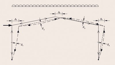

Second-order effects increase the deflections, moments and forces beyond those calculated by first-order analysis. Sensitivity to second-order effects needs to be assessed for each designed structure.
When second-order effects are significant, two options are possible:
- a rigorous second-order analysis (i.e. in practice, using an appropriate second-order analysis software)
- an approximate second-order analysis (i.e. a modified first-order analysis with appropriate allowance for second-order effects).
In the second method, also known as 'modified first-order analysis', the applied actions are amplified, to allow for second-order effects while using first-order calculations.
[top]Elastic analysis
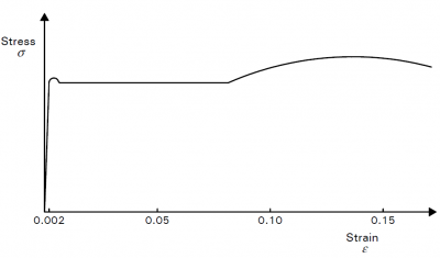

Elastic analysis programs are the most widely used for structural analysis and are based on the assumption that the material which is being modelled is linear-elastic., therefore the limiting stress is the value corresponding to the strain of 0.002, up to which steel behaves as a linear material. The appropriate value of the elastic modulus has to be provided in the analysis. BS EN 1993-1-1[1] allows the plastic cross-sectional resistance to be used with the results of elastic analysis, provided the section Class is Class 1 or Class 2.
[top]Plastic analysis
Plastic analysis relies on the formation and rotation of hinges, therefore it demands Class 1 sections. Plastic hinge rotations occur at sections where the bending moment reaches the plastic moment or resistance of the cross-section at load levels below the full ULS loading.
Plastic analysis is generally used only for portal frame design, where it results in a more economical frame than an elastic analysis. This is because plastic analysis allows relatively large redistribution of bending moments throughout the frame, due to plastic hinge rotations. This redistribution 'relieves' the highly stressed regions and allows the capacity of under-utilised parts of the frame to be mobilised.
[top]References
- ↑ 1.0 1.1 1.2 1.3 BS EN 1993-1-1:2005+A1:2014, Eurocode 3: Design of steel structures. General rules and rules for buildings, BSI
- ↑ 2.0 2.1 2.2 BS EN 1993-1-8:2005. Eurocode 3: Design of steel structures. Design of joints, BSI
- ↑ 3.0 3.1 3.2 UK NA to BS EN 1993-1-8: 2005: 2008, UK National Annex to Eurocode 3: Design of steel structures. Design of joints, BSI
[top]Further reading
- Steel Designers' Manual 7th Edition. Editors B Davison & G W Owens. The Steel Construction Institute 2012
- Guidelines for the use of computers for engineering calculations, IStructE, 2002.
[top]Resources
- SCI P100, Design of Composite and Non-composite Cellular Beams, 1990
- SCI P183, Design of Semi-continuous Braced Frames, 1997
- SCI P281, Design of Curved Steel, 2001
- SCI P355 Design of Composite Beams with Large Web Openings, 2011
- SCI P358, Joints in Steel Construction: Simple Joints to Eurocode 3, 2014
- SCI P397 Elastic Design of Single-span Steel Portal Frame Buildings to Eurocode 3, 2013
- SCI P398 Joints in Steel Construction: Moment-resisting Joints to Eurocode 3, 2013
- SN045a-EN-EU Access Steel. NCCI: Column base stiffness for global analysis
- Steel Buildings, 2003, (Publication No. 35/03), BCSA, Chapter 2
[top]See also
- Floor vibrations
- Allowing for the effects of deformed frame geometry
- Multi-storey office buildings
- Continuous frames
- Trusses
- Portal frames
- Simple connections
- Moment resisting connections
- Braced frames
- Steel material properties