


50-60 Station Road, Cambridge
Article in NSC January 2018

Peak development
Cambridge’s tallest office block will form the centrepiece of the city’s ambitious CB1 master plan.
Cambridge is currently a hive of construction activity, so much so that in some quarters it has even been dubbed ‘Cranebridge’. The famous university city is expanding as new residential, commercial, as well as educational and science establishments are springing up, predominantly around the outskirts. One of the largest schemes however, is being undertaken right in the city centre, next to the main railway station. Known as CB1 and covering an area of 23 acres, the development will eventually provide a new city quarter on land that had mostly been occupied by railway sidings and a mill.
As well as a new station square and transport interchange, CB1 will provide Grade A office blocks, residential and student accommodation, retail units and hotels. CB1 is currently delivering what is said to be the city’s tallest office block, which is designed to accommodate a European or UK regional headquarters and will attain a BREEAM ‘Outstanding’ rating.
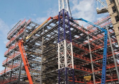
The steel-framed 50/60 Station Road will provide 15,100m2 of office space and ground floor retail units, within an eight and nine storey block, both positioned above an underground car park. Originally designed as two separate buildings, the plans developed over time and finally the two structures were joined with an eight-storey link structure to form one large frame. This is said to have increased construction efficiency while delivering a far greater floorplate. Located opposite the station, this project is in terms of height CB1’s peak building and a centrepiece, as future developments will progressively step down in size the further they are from the station.
50/60 Station Road’s steel frame comprises cellular beams used in conjunction with composite metal deck flooring; this has helped to create the desired spans of up to 12m. The lateral stability of the structure is provided through concrete core structures, into which the steel frame connects. There are two cores; the largest one (east) positioned within the nine-storey block contains all of the lifts, while a small stairwell core is located in the eight-storey part. Below ground the structure is supported on piled foundations with steel sheet piles creating the perimeter of the basement.
Explaining why this project is being constructed with a steel framing solution, Galliford Try Senior Projects Manager Fergus Anscombe says: “We have spans of up to 12m and creating these long column-free spaces is easier with steelwork as the floor-to-ceiling heights are restricted by local planning. We’ve also made use of cellular beams throughout the building; they accommodate services, thereby helping to keep the structure within its specified height restriction.”
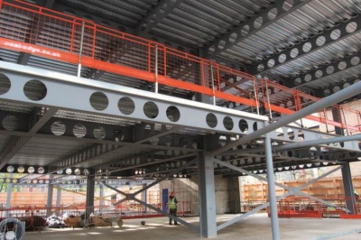

Mott MacDonald Senior Structural Engineer Roger Faires adds: “The project also benefited from the involvement of Billington Structures who worked to refine the cellular beams using plain beams and its in-house plasma cutter to bring about more commonality in the structure.”
Work on the project began last year with Galliford Try demolishing a row of Victorian terraced houses that occupied part of the site. In readiness for excavating the basement car park, a series of 10m-deep sheet piles were then installed to help form the basement perimeter wall.
The steel frame and basement slab are supported on 3m deep pile caps which, in turn, are supported by 190 x 750mm diameter CFA piles extending 23m down to suitable strata. The 9m x 12m steel column grid pattern, used pretty much right through the scheme, was deemed suitable for the car park, offices and retail units. The project’s two stability-giving concrete cores were next to be constructed.
“As the west core is smaller and was quicker to construct, we started the steel erection programme at this end of the scheme,” says Mr Anscombe. “This worked well for our on-site logistics and allowed the earliest availability to erect 50% of the structural steel. The steel erectors had one part of the site to themselves, while the east core was still being built at the other end.” Galliford Try says working in this sequence enabled steelwork contractor Billington Structures to complete the first half of the project faster than originally expected, which had the positive knock-on effect of allowing the follow-on trades to start early.
The entire steel frame will be completed during January 2018 with all the steelwork being lifted into place via the site’s two tower cranes. According to Billington Structures the heaviest steel member was 8t, but this had to be reduced due to the capacity of the tower cranes. The only time the company needed to use other cranes was when it hired a 220t mobile to lift its MEWPs into the basement from where they helped erect the entire frame.
Having completed its initial steelwork, Billington Structures is scheduled to return to site later this year to complete some final elements. This includes some basement infill work and a car park ramp, as well as a cantilevering pod attached to the building’s link structure.
The pod has to be retrofitted as its main support, as well as bracing, comes from the building’s completed floors in the adjacent link structure. The one-storey pod cantilevers by up to 6m from the first floor and overhangs a colonnade that runs along the front of the building. Measuring up to 8m-wide, the fully-glazed pod is formed with a series of curved and straight beams, creating a highly visual structure that will seem to float above the ground floor.
50/60 Station Road is due to complete by April 2019.
BIM aids cost-effective cellular beam design
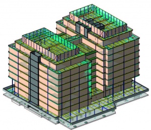

Building Information Modelling (BIM) using Tekla Structural Designer (TSD) helped with the project’s rationalisation of its cellular beams.
“The top two floors of each block include transfer beams for inset floors. The original design was for double beams to support the inset columns. Using TSD we replaced a number of double beams with Westok plate beams, which could be designed within the model. The model also allowed us to react quickly to the early design changes including removing the original second basement” explains Mott MacDonald Senior Structural Engineer Roger Faires.
Using the drawing function, information could be sent to the mechanical engineer to confirm web penetration requirements with their service route requirements. The section was then exported to Revit and the information could be used to ensure web penetrations were displayed accurately on drawings.
Using this process savings were made on steel weight and the number of connections, while allowing a more integrated design.
| Architect | Grimshaw Architects |
| Structural Engineer | Mott MacDonald |
| Steelwork Contractor | Billington Structures |
| Main Contractor | Galliford Try |
| Main Client | Brookgate |