


City University London, CitySport
Article in Construction News Special – Steel Spotlight, 11/04/14

Sports hall roof puts trust in trusses
By Ruby Kitching
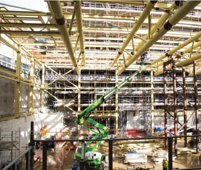
The new sports hall at City University’s Goswell Road site will feature trusses spanning 28.5m while supporting a heavily loaded ‘green roof’. Redeveloping City University’s worn-out Halls of Residence buildings at 122 to 130 Goswell Road, London will allow 318 more students to be housed and the former Sadlers Sports centre to be rebuilt.
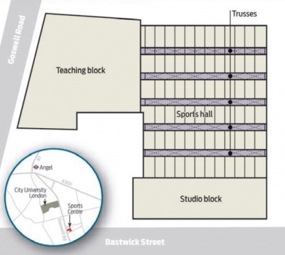
The 0.6 ha site is bounded by Bastwick Street to the south, Pear Tree Street to the north, Goswell Road to the west and neighbouring buildings to the east. Located just 450m from City’s main campus at Northampton Square, the new development designed by architect TP Bennett and structural engineer Campbell Reith for client City University London aims to set a new high standard for student facilities.
The steel framed CitySport (sports centre) comprises a single-storey multi-sports hall, five-storey teaching block and two-storey studios. The publicly accessible sports centre is located to the west of the residential blocks and straddles the corner of Bastwick Street (to the south) and Goswell Road to the west. The sports hall can accommodate six badminton courts and has been designed to meet the height and span requirements for basketball, indoor football, hockey and netball at county competition level.
Construction of CitySport is currently focussed on the studios as the hall and education block are now structurally complete.
Main contractor Mace began work on the sports centre site in August 2012 by demolishing the existing Sadlers sports centre as well as a single-storey building which contained the set for TV cookery series Masterchef. Ground level was reduced by about 4m to create a lower ground floor using Kingpost–supported retaining walls around the perimeter.
Ground structure support
Mace project director Mick Delaney says: “A temporary support structure was required to support the existing ground retaining structures while the permanent structure was constructed. Once the permanent structure had reached its required structural integrity the temporary structures were removed.”
The neighbouring property at 116 to 120 Goswell Road was also underpinned and propped during excavation. A further 15m wide by 35m long and 3m deep basement below lower ground level was also excavated beneath the sports hall to accommodate plant.
Above ground, steel plates were cast into the lift and stair cores ready to receive the steel frame in the teaching block and studio building.
“We started on site in November 2013 and our first job was to survey the positions of the cast-in plates (in the teaching block cores) and then weld fin-plate connections onto them,” says Billington Structures project manager Kevin Meers. “Beams could then arrive on site and be bolted to these fin plates”.
Westok cellular beams 650mm deep are used in the floor structure for both the teaching block and studio building. “We have been able to coordinate the openings with the services using a standard beam depth,” says Campbell Reith partner Nicholas Stockley.
Smaller beam depths could have been used, but the apertures in the beams provided future flexibility for different arrangements of services. Construction of the teaching block was split into four work areas or ‘phases’, when Billington Structures would build the structure from ground to roof level before starting work on the next phase.
Contained operations
“Working in designated areas contained our operations and gave more space for other work to take place elsewhere on site,” says Mr Meers. Once Billington Structures finished one phase, other trades could move in and the steelwork contractor could move a stage on.
After spending 16 weeks – four weeks per phase – on the teaching block, Billington Structures then moved on to erecting the sports hall. The 28.5m wide by 35m long hall roof is supported by five, 28.5m long trusses. The trusses are 2m deep and are triangular in section with twin top chords and a single bottom chord, all made from 450mm diameter circular hollow sections. Cross-bracing members are 150mm diameter CHSs.
Four cross-bracing members spring from a single point on the bottom chord and fan out to meet the twin top chords. The trusses are connected back to the first floor of the teaching block or to 305mm by 305mm columns, depending on where they are located.
“The trusses arrived on site in three sections, each about 10m long and were lifted in place by the tower crane,” explains Mr Meers. Two temporary tower frames located on the ground floor supported these trusses until they were fully connected.
Starting from the north end of the building, the first 10m section of truss was connected to the first floor of the teaching block on its western end and supported by temporary tower A at the other end. The central truss section was then lowered and supported onto temporary tower A and connected to the free end of the first truss. The other end of the central truss was lowered onto temporary tower B. Finally, the last section of truss was lowered onto temporary tower B and connected to the free end of the central truss at one end, while the other end (on the eastern edge of the hall) connected to a steel column.

Trussed towers
Mr Meers explains the procedure for the remaining four trusses: “When all the truss connections were made on each truss section, the top 1m of the two temporary towers could be detached, allowing the main part of the tower to be shifted to the next truss position. The top 1m was then reassembled ahead of the next truss section being installed.”
Bolted connections between truss sections are hidden within the depth of the CHSs by curved cover plates. These are welded to the CHSs and painted to make the whole truss appear a single entity.
The trusses have been detailed to allow service ducts to pass between cross-bracing locations. Three of the five trusses to the north are slightly longer as they connect to the teaching block floor plate rather than a column on their western end (see above left). “To ensure all the service ducts would line up and keep the trusses looking identical from an architectural perspective, the trusses are made longer by extending the top chords,” Mr Stockley says.
He explains that there was also limited depth available to accommodate this truss because the hall required a 9.1m clear height for competitions, but planning regulations had put a strict limit on the overall height of the building. A Toblerone-shaped steel truss was architecturally favoured and its 2m depth met all other design constraints.
Further, only a high-strength, lightweight steel structure could span the sports hall and support the heavily loaded ‘green roof’, which is made up of a considerable depth of growing medium – 150mm of substrate weighing around 200kg/m2 – and vegetation.
With gutters on the western and eastern ends of the sports hall, each 28.5m truss is also slightly pitched at its midpoint. This was achieved by offsetting the connection between the roof beams and the top truss chords. “There was a lot of co-ordination between the architect, Billington Structures and us to ensure the truss appeared horizontal from below, but had a slight fall for drainage,” says Mr Stockley.
Commenting on the suitability of a steel frame structure for the teaching block and studio spaces, Campbell Reith associate Will Shaw says: “There was no logical alternative other than to build CitySport using a steel frame. “We wanted open plan spaces and needed steel to span those distances. (In the teaching and studio blocks) we could have used post-tensioned slabs, but that would have meant bringing in another trade onto (an already crowded) site.”
Completion of the CitySport is planned to coincide with the accommodation blocks, which will be completed in August ready for City University London’s September 2014 intake of students.
| Architect | TP Bennett |
| Structural Engineer | Campbell Reith |
| Steelwork Contractor | Billington Structures |
| Main Contractor | Mace |
| Client | UKSA City University |