


Siemens wind turbine blade manufacturing facility, Hull
Article in NSC July/August 2016

The winds of change
Part of the wider Green Port Hull vision, Siemens is building a large steel-framed blade manufacturing facility on the River Humber.
By Martin Cooper
Forming the centrepiece of the Green Port Hull vision, which seeks to establish the city and the East Riding of Yorkshire as a world-class centre for renewable energy, the Siemens wind turbine blade manufacturing facility will create 1,000 jobs and is said to be the biggest influence of the local economy for generations. Located at Hull’s Alexandra Dock, the 40,000m2 facility will mould 75m-long wind turbine blades, (the world’s longest blades), paint them, drill them and then store them on a specially prepared dockside lot ready to be delivered offshore for final assembly.
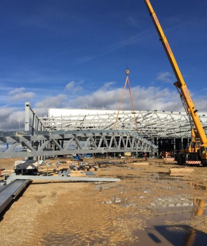
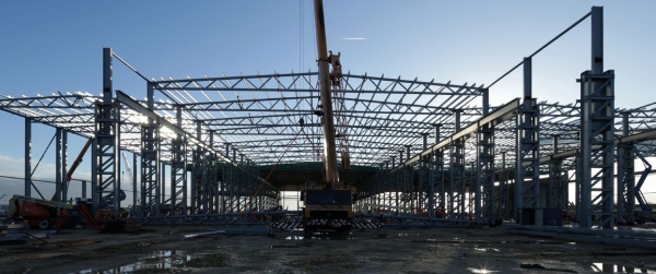
All of the parts that make a wind turbine, including nacelles - the fuselage that connects to the blades and contains the generating components - along with the masts will also be stored on the site. This will allow Siemens to dispatch all of the constituent parts that make up a wind turbine from one location, once blade production begins later this year. The blade manufacturing process will be housed in a large steel-framed multi-span braced structure measuring approximately 300m long × 116m wide.
In order to get planning permission the site had been previously raised 200mm above the flood plain with a 1m-deep stone plateau as part of the preliminary works. VolkerFitzpatrick, which is managing the build of the facility, started on site last August, just as the installation of 4,000 driven piles was coming to an end.
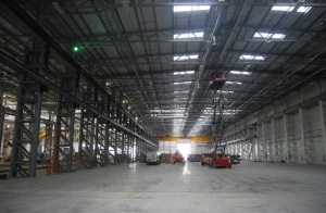
Clear open spans of up to 36m are vital for the manufacturing process
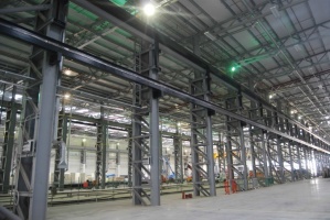
Crane beams are supported on twin lattice columns


“The building is essentially divided into two main parts - a four span manufacturing and painting area, and a three span finishing area,” says VolkerFitzpatrick Operations Manager Ian Simmons. The former area has two manufacturing/ moulding lines contained within 36m-wide spans. In between there is a 22m-wide painting span while, attached along the eastern side of the building, another 22m-wide span will accommodate storage and warehousing.

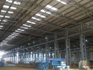
All of these spans are formed by a series of twin braced lattice columns supporting a series of roof trusses that measure up to 2.1m deep. All of these spans will accommodate cranes with the two widest spans featuring 40t-capacity overhead cranes running on crane rails that are connected to the main lattice columns. All of the spans have smaller console cranes that run on separate rails that are also connected to the steel main frame.
“As with many industrial buildings this is a bespoke steel frame designed and tailored around the manufacturing process and the way the cranes will be operated,” explains Waterman Structures Regional Director Mark Billington. “Before designing the steel frame we had to gather information on whether the cranes would operate separately or in tandem in order to determine the loadings and fatigue on the steelwork.”
Twin lattice braced columns were chosen for their stiffness and ability to carry heavy loadings, the inner part of the twin columns, where necessary, supports the high-level crane rails, while an outer part extends up to the roof, connecting with the roof trusses.
Because of the need to incorporate cranes, the northern or manufacturing part of the facility has a height to eaves of 15m. The southern part of building, or finishing zone, has no overhead cranes and consequently the roof level for this zone drops down to 10m. This part of the building has the same width as the northern zone but is formed with just three spans, two at 47m and a third measuring 22m wide. As this area does not have to support any cranes, the truss supporting columns are not twin lattice sections but 610 UBs.
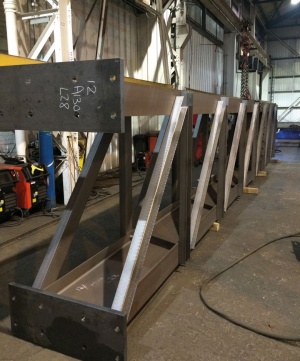
“The longest trusses were brought to site in three sections, while the 22m-long trusses were fabricated in two pieces,” explains Caunton Engineering Contract Manager Michael Firth. “Once on site they were bolted and assembled into complete trusses and then lifted into place by a single mobile crane.” Caunton Engineering had up to five mobile cranes working on its steel programme, with multiple spans of the building being erected at any one time.

The facility also features an attached two-storey office block that is structurally independent and gains its stability not from bracing but from a series of moment frames. It features a steel frame supporting precast planks on the beams’ bottom flange - a construction method chosen as the client wanted exposed soffits.
The first wind farm to receive turbines from the Hull facility later this year is expected to be Dudgeon, which is located off the Norfolk coast
Alexandra Dock – the whole storey
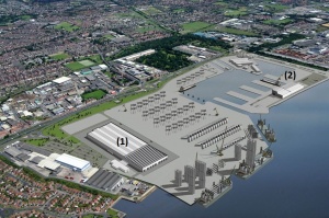

Associated British Ports, which owns the site, has appointed Graham Lagan Construction Group JV to develop the overall Alexandra Dock for the Siemens facilities.
The blade manufacturing facility (1) is being built under a separate contract and so all around this site other important works are ongoing. The JV is responsible for the partial reclamation and infill of the existing dock, the construction of three new berths and a roll-on roll-off ramp.
On the opposite side of the dock to the blade facility, a separate steel-framed structure for the servicing and refurbishment of blades is being erected (2).
The lateral stability of large industrial buildings
By Dr Richard Henderson, SCI

The (northern) manufacturing area of the Siemens factory has four bays with two 40t electric overhead travelling (EOT) cranes travelling on runway beams supported by double lattice columns. This arrangement conveniently allows the runway beam vertical reaction to be transferred to the ground directly through one leg of the double column. The estuary-side site requires piled foundations and this allows overall building stability in the direction perpendicular to the runway beams to be provided by fixed base columns. The double lattice columns are laterally stiff by virtue of acting as the tension and compression booms of a vertical cantilever truss. The push-pull in the columns is transferred via pile caps into the piles. The column leg not supporting the crane runway beams continues upward to support the roof trusses which are simply supported between columns. In the orthogonal direction, K bracing is provided to stabilize the building.
The lower (southern) finishing area of the building is separated from the manufacturing area by a movement joint. No EOT cranes are required so double columns are not provided. UB columns are adopted and lateral stability is provided by vertical bracing in the three perimeter walls. Bracing is also provided where the finishing area abuts the manufacturing area. The roof is braced in plane so the building forms a braced box.
For a structure on a site where piles are not necessary, fixed-foot columns are more difficult to achieve because of the flexibility of pad foundations. In these circumstances it may be appropriate to design the columns to have pinned feet and frame into the roof trusses such that the columns and roof trusses form portal frames with a stiff truss rafter. The column stiffness therefore controls the sway deflection. A space free from bracing can be achieved if there is a regular array of columns in each direction and the lateral stiffness is similar in each of the orthogonal directions.
A conventional portal frame structure is similarly designed as continuous in the plane of the frame and achieves stability through the moment connections between columns and rafters. The portal frame rafters are more flexible than the truss rafters and therefore contribute to the flexibility of the frame. In the orthogonal direction, the portal frames are often braced or portalised bays can be introduced if internal bracing interferes with the building function.
These examples show how the choice of stability system of the building is driven by the type of foundation, the use of the enclosed space and the opportunity for the use of bracing.
| Architect | Pringle Brandon Perkins+ Will |
| Structural Engineer | Waterman Structures |
| Steelwork Contractor | Caunton Engineering |
| Main Contractor | VolkerFitzpatrick |
| Main Client | Siemens |