


Olympic Stadium, London
Structural Steel Design Awards 2012 - Award
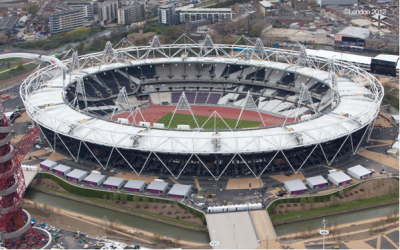

The brief was for a stadium of 80,000 capacity to host the London 2012 Olympic and Paralympic Games with the flexibility to transform into a smaller 25,000 capacity venue for the legacy. The requirement for a temporary 55,000 seat structure resulted in a lightweight demountable steelwork design consisting of trussed rakers on raking columns, which reduced the footprint and minimised the impact on the spectator circulation areas below the terracing.
To provide flexibility in both construction, dismantling and possible legacy uses the roof is structurally independent from the terrace structure. The roof consists of a 900m long ring truss supported on a series of inclined tubular columns. As the structure needs to be demountable, all site connections including those between the steel and precast concrete units are bolted.
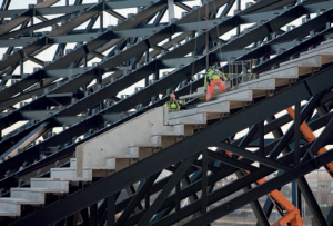
The terrace superstructure consists of precast concrete units resting on large raking lattice girders, which are supported on concrete shear walls at the front and by raking steel columns along the span. The terrace girders were detailed as factory welded units and made as large as possible but within the easily transportable limits. The design was rationalised through the design development period to minimise the number of components and allow simple connections to be used.
The roof covering consists of a PVC fabric supported on a cable net with an inner tension cable ring and an outer steel compression truss. The outer ring truss is approximately 900m long and 12m deep and is supported at 32 positions by inclined raking tubular columns down to ground level. The ring truss was designed to be fully bolted with simple flange connections for ease of erection and dismantling, and the individual sections are faceted rather than curved which reduced the fabrication cost.

The inner cable tension ring consists of ten 60mm diameter cables connected by steel brackets at 6m centres which in turn support a continuous walkway. The ring truss is supported by 80mm diameter suspension cables from the top boom of the compression truss, and the whole system is tensioned by 70mm tie down cables connected to the bottom boom of the compression truss. Sitting on top of the inner cable ring are 14 large pyramidal lighting towers, each 30m high and weighing 34 tonnes, which are restrained to each other and back to the compression truss with a secondary cable system.
The terrace steel structure was erected on two fronts working from the south east corner using crawler cranes, followed closely by the installation of the precast terrace units using separate tower cranes. The precast units were installed by the steelwork contractor and, to minimise any site clashes, all the units were incorporated into the steelwork model during the detailing stage.
The ring truss was delivered to the central area as individual components and assembled in jigs into sections 30m long weighing approximately 100 tonnes each. The leading edge of the truss had to be supported by temporary works from the terrace structure until the ring truss was completed, at which point it became self stable.

The cable tension ring was assembled at low level on a temporary platform at terrace level. The suspension and tie down cables were fixed at high level to the compression truss and laid out across the terrace using temporary mats to prevent damage to either the precast units or the cables themselves. When the inner ring assembly was complete, temporary pulling cables were fixed to the ends of the suspension cables and attached to 32 separate strand jacks located on the top of the inner tension ring. The 32 strand jacks were then operated simultaneously which pulled the inner ring into tension and raised the ring truss of the temporary platform. The tie down cables were connected during the lifting process. Once the net was suspended at its final level, the permanent connections from the suspension cables to the inner ring were made and the pulling jacks and temporary cables removed.
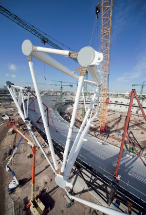
Erection of the lighting towers was extremely challenging due to the weight and lifting radius, and the fact that they were not self-stable until the final high-level circumferential cable had been connected and pre-stressed. The 14 lighting towers were fully assembled and fitted out at ground level. The top 'A' frame assembly was lifted off the ground with a 600t capacity crawler crane. The pair of 18m long legs and a 40m long temporary strut were then lifted and fitted to the underside of the 'A' frame using a second crane. Each of the assemblies then weighed 43 tonnes and was lifted with a 600t crawler crane.
Following installation of all 14 towers on their temporary supports the upper high level circumferential stability cables and the rear stability cables were fixed and pre-stressed. Before the temporary struts could be removed, verification that the cables had been pre-stressed to the required load, and that the stability of the lighting towers had been transferred to the cable net system, was required.
The final erected geometry of the roof and lighting towers was verified by using a full 3D laser scan of the entire stadium structure. The cable net pre-stress forces were also independently checked using cable vibration measurements to calculate the natural frequencies and forces in the cables.
The Olympic Stadium was completed within budget and handed over three months early.
| Architect | Populous |
| Structural Engineer | Buro Happold |
| Steelwork Contractor | Watson Steel Structures Ltd (now Severfield (UK) Ltd.) |
| Main Contractor | Sir Robert McAlpine |
| Client | Olympic Delivery Authority |
Judges' comments
The requirement for a severe reduction in capacity after the Olympics has resulted in a lean design, with expressed exo-skeletal steel superstructure. This has been stripped of the usual layers of periphery accommodation.
There is clear definition between different structural systems, with white-painted tubular roof, and black steelwork for the seating bowl.
The architecture provides clarity to the structure, and its subsequent disassembly.