


Modelling and analysis of beam bridges
The majority of highway bridges are beam structures, either single spans or continuous spans, and composite bridges are of either multi-girder or ladder deck form. Determining the principal effects of the various loading combinations can often be achieved with a 2-dimensional analytical model but for a more comprehensive analysis a 3-dimensional model is needed. This article reviews the appropriate analysis and modelling techniques for typical steel-composite bridges in the UK.

[top]Modelling options for a typical multi-beam bridge
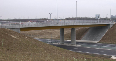

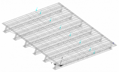
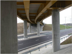
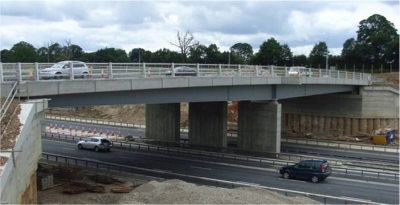
Trinity Overbridge on the A120
(Image courtesy of Atkins)
There are three modelling options for a typical multi-girder steel composite bridge:
- Line beam
- Grillage
- Full finite element model
A line beam is a fairly crude tool. It does not take account of transverse distribution, it gives no output for transverse design (e.g. slab or bracing) and does not consider skew effects. It would not be recommended for detail design, but is a useful tool for preliminary design.
Use of a grillage model is suitable in many situations. Use of a finite element model will give more detailed results, especially for non-uniform beams.
While grillage analysis is widely used, and is still considered to be most appropriate for most bridge decks, it is recognised that finite element analysis programs are becoming more widely available and easier to use. Also, the Eurocode requirements for checking lateral torsional buckling may make a finite element buckling analysis essential for checking the wet-concrete construction load case.

[top]Grillage analysis
[top]Grillage analysis: overview
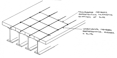

The grillage model is a common form of analysis model for composite bridge decks. Its key features are:
- It is a 2D model
- Structural behaviour is linear elastic
- Beam members are laid out in a grid pattern in single plane, rigidly connected at nodes
- Longitudinal members represent composite sections (i.e. main girders with associated slab)
- Transverse members represent the slab only, or composite section where transverse steel beams are present
[top]Grillage analysis: member layout
The following guidance is offered for choosing the grillage layout:
- Keep grid dimensions approximately square
- Use even number of grid spacings
- Grid spacing not more than span/8
- Edge members along line of parapet to facilitate load application
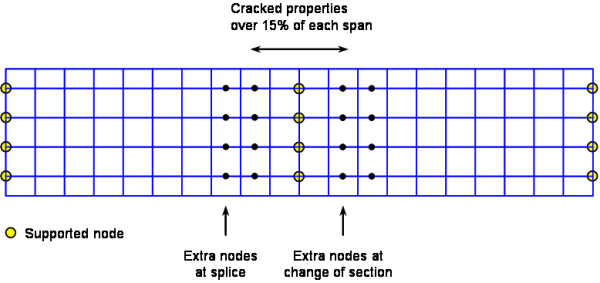
- Insert additional joints for splice positions (usually assumed to be 25% of span from piers)
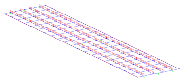
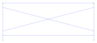
For a 2-span bridge, as illustrated above, an appropriate layout would be as shown below.

[top]Grillage analysis: application of loading in stages
At least three different grillage models will be required to model the response of the structure to the range of permanent and variable actions:
- A ‘steel-only’ model: The self weight of the steel beams and the weight of the wet concrete during construction are applied to a steel-only grillage model. Longitudinal members represent the steel girders only, while transverse members are not usually necessary (they may be set as ‘dummy’ members to keep the same model arrangement as composite models).
- A ‘long term’ composite model: The permanent actions applied to the completed structure (chiefly the superimposed dead loads such as surfacing, and the restraint of curvature due to shrinkage) are applied to a long-term composite model. The section properties of the longitudinal composite members and the transverse members representing the slab are calculated using long-term concrete modulus of elasticity of the concrete. Where the slab is in tension, cracked section properties may be needed.
- A ‘short term’ composite model: The transient actions (mainly the vertical loads due to traffic) are applied to a short-term composite model. Section properties are calculated in the same way as for the long-term model but using the short-term modulus of elasticity. Again, cracked section properties may be needed where the slab is in tension.
Note that BS EN 1992-1-1[1] gives a slightly different long-term modulus of elasticity of concrete for shrinkage loading, so theoretically there should be a fourth model for analysing shrinkage effects. However, the modulus is not significantly different from the ‘ordinary’ long term value and it is reasonable to apply the shrinkage restraint moments to the long term model for determining the secondary moments in the beams. However, appropriate section properties for shrinkage should be used for calculating stresses due to those effects.
[top]Grillage analysis: section properties
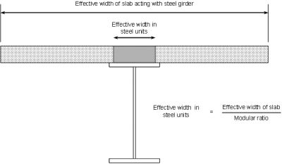

It usual to calculate all section properties in ‘steel units’, using a transformed area for the concrete flange (divide by the modular ratio n = Es/Ec). The following section properties are needed for each different cross section:
- Steel only: steel girder properties only
- Long term composite: concrete area transformed for the long-term modular ratio
- Short term composite: concrete area transformed for the short-term modular ratio
- Cracked properties (in hogging regions): reinforcement area only taken as effective in slab section
For the uncracked section properties, the reinforcement in the slab may be ignored.
A typical transformed section is shown right.
[top]Extent of cracked properties
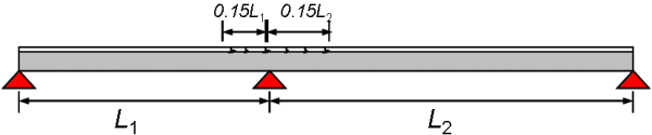
Where the ratios of the lengths of adjacent spans are at least 0.6, the allowance for cracking of the slab in hogging regions may be made by using cracked section properties for 15% of the span either side of an intermediate supports, as shown below. This covered by BS EN 1994-2[2], clause 5.4.2.3.

[top]Shear lag in concrete flanges
The effective width of concrete flanges is based on a width of slab equal to Le/8 outside the outer stud, either side of the beam, where Le is the distance between points of contraflexure. This definition is given in BS EN 1994-2[2], clause 5.4.1.2, where approximate values of Le are given. Note that shear lag does need to be considered at both ULS and SLS (the same effective width is used for both limit states).
[top]Grillage analysis: application of loads
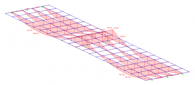
Permanent actions (self weights) are apportioned between longitudinal members by simple statics. A graphical view of a typical permanent loads applied to a grillage model is shown below (left).
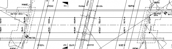
Traffic loads are usually derived by ‘auto-loading’ programs that are part of most analysis software. These programs use influence surfaces to determine the extent of uniformly distributed loads and the positions of tandem systems and special vehicles. A typical influence surface for a midspan bending location is shown below (right).
The user decides which positions on the model are most significant for design (e.g. midspan, splices and support positions) and requires the influence surfaces to be generated for those positions; the auto-loader then determines the positions where loads are applied for the most onerous effect.
Graphical view of permanent loads applied to model
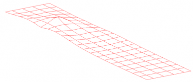
Typical influence surface for bending moment at mid-span in a 2-span, 4-beam bridge


[top]Grillage analysis: output
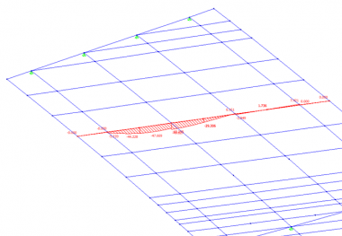
The main aim of any global bridge analysis is to produce output that can then be used in section analysis and design. Typically this output will be bending moments, shear forces and torques (where significant) in the main beams. Deflections will also be required for precamber calculations. The output is likely to be either graphical or tabular both are useful. The graphical output allows the peak moments and shears to be quickly established by eye and also allows the designer to make a visual check of whether the model is behaving as expected. The tabular output can be useful for post-processing by spreadsheet and simultaneous reading of coexistent load effects. However, the designer should use judgement of where the critical locations are on the structure to avoid excessive amounts of output data and post-processing.
Typical graphical view of bending moment output
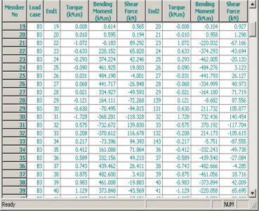
Typical output of load-effects from grillage analysis


[top]Grillage analysis: other considerations

The following also need to be considered:
- Global effects for transverse slab design: Take load effects on transverse members from the grillage model and add to effects from local analysis (e.g. Pucher Charts. See SCI 356). Any loads applied to the grillage should be applied to joints only for this purpose to avoid any inaccurate double counting of local effects.
- Bracing: Bracing is usually modelled with a shear-flexible member (is conservative to use a member that does not allow for shear flexibility), with equivalent properties calculated from a plane frame model. The plane frame model can also be used to for the bracing design using deflections, from the grillage model, imposed on the plane-frame model and restraint forces as appropriate.
- Supports: All supports provide only vertical restraint in 2D grillage. The effects of non-vertical loads must be assessed either by hand or by an alternative model.
- Hand checks: Hand checks should be carried out to validate the model, for example checking bending moments under uniform loading and checking support reactions
- Combined global analysis and section design software: Some software offers combined global analysis and section design capability. Designers should ensure that they understand the theory behind the design of beam sections and carry out checks on the output.

[top]Grillage analysis: variations
[top]Skew bridges
Many bridges are skew in plan and the grillage model is able to accommodate this arrangement in one of several ways. Consider the typical plan of a skew bridge shown below.

For small skew angles, the mesh can be aligned with the skew, as shown below.

For larger skew angles, the behaviour of skew elements becomes inaccurate and it is better to return to an orthogonal mesh. At the ends, the skew must be accommodated.

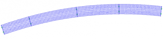
[top]Curved bridges

It is relatively common for bridges at grade separated interchanges and other locations where space is restricted to have significant plan curvature.
For such situations, curved grillages can be used, although care is needed in choosing the layout and in considering the analysis results as torsional effects in the slab are not easily separated from warping effects in the steel girders. Additionally, the effects of the horizontal ‘radial’ forces in the in steel flanges will need to be added in after grillage analysis.

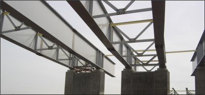
[top]Variable depth girders
Variable depth girders, such as that illustrated below can easily be accommodated in a grillage model by varying the section properties along length of longitudinal members.

(Image courtesy of Atkins)
[top]Ladder decks
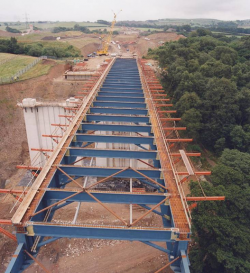

Ladder decks, such as that shown right can be modelled using grillages.
In the grillage model for a ladder decks:
- The main longitudinal members represent full composite section
- Intermediate longitudinal members represent slab only
- Transverse members will generally represent the composite section including cross-beams. Sometimes intermediate slab-only members may be included, in-between the composite transverse members.
A 3D model is likely to be required to model interaction between cross-girders and main girders, particularly the determination of ‘U’ frame stiffness and effects on cross-girders due to local application of special vehicles.


[top]Integral bridges
For an integral bridge, one could use 2D grillage with rotational spring supports at the integral supports in conjunction with 2D plane frame model for temperature effects. Alternatively a 3D model with grillage section for deck and vertical sections for abutment and foundation could be used.
[top]Elastic critical buckling analysis for wet-concrete loadcase

BS EN 1993-2[3] gives no formula for determining the lateral torsional buckling slenderness of paired steel beams with torsional bracing, where the pair of girders is liable to buckle as a pair in sympathy with each other rather than between restraints. This is the usual scenario for wet concrete loading. There are two options that can be considered:
- Calculate the slenderness using an FE elastic critical buckling analysis
- Use the simplified rules for the flexibility of torsional restraints derived from BS 5400-3[4] (these are available in Eurocode format in SCI P356).
For an FE analysis, the user needs to view buckling modes to find the lateral torsional buckling mode – one may find web or flange buckling modes occur before lateral torsional buckling modes.
An FE analysis is likely to give significant benefit over the simplified approach, as discussed in beam design.
Further guidance on how to determine the buckling resistance of steel plate girders in composite bridges during construction (the bare steel stage) and in service (when the deck slab acts as a top flange) is available in ED008
[top]Finite element modelling
As it is likely that a finite element model will be required for the elastic critical buckling check, one could consider using a full finite element model for all the analysis. This would also have the advantage that the structural response is potentially better modelled. However, there are a number of disadvantages including:
- Longer set-up
- More chance of errors
- Longer to extract results
- More practice required to use with confidence
- Debugging harder
- Peak support moments could be underestimated
Where it is decided the use a finite element model, the following guidance may be of help:
- Coarse mesh likely to be adequate
- Keep mesh as square as possible
- More thorough planning required
- Thick shell elements for beams and slabs, beam elements elsewhere (e.g. for bracing)
- Alternatively could use beam elements for the component plates for the steel beams
- More checking required
- Anisotropic properties required in cracked regions
[top]Conclusions
The grillage is the commonly used model for bridge decks and it is relatively easy to use. However, a finite element model is quite likely to still be required as well for elastic critical buckling analysis of the steel girders supporting wet concrete loading. Consequently, a finite element model could be considered for all analysis, which would also have the possible advantage of better modelling of structural response. However, there are some disadvantages of this approach so many designers use a grillage for the main analysis and only use a finite element model where absolutely necessary.
[top]References
- ↑ BS EN 1992-1-1:2004+A1:2014 Eurocode 2. Design of concrete structures. General rules and rules for buildings, BSI
- ↑ 2.0 2.1 BS EN 1994-2:2005, Eurocode 4. Design of composite steel and concrete structures. General rules and rules for bridges, BSI
- ↑ BS EN 1993-2:2006, Eurocode 3. Design of steel structures. Steel bridges, BSI
- ↑ BS 5400-3:2000 Steel, concrete and composite bridges. Code of practice for design of steel bridges. BSI
[top]Resources
- Iles, D.C. (2010) Composite highway bridge design. (P356 including corrigendum, 2014). SCI
- Iles, D.C. (2012) Determining the buckling resistance of steel and composite bridge structures. (ED008). SCI
- Iles, D.C. (2012) Design of composite highway bridges curved in plan. (P393). SCI
[top]See also
- Multi-girder composite bridges
- Ladder deck composite bridges
- Integral bridges
- Bridges - initial design
- Design of beams in composite bridges
- Bracing systems
- Connections in bridges
- Plan curvature in bridges
- Skew bridges