


6 Bevis Marks, London
Article in NSC October 2013

Foundation reuse creates sustainable landmark
An extensive sustainability agenda, incorporating the reuse of existing piles, resulted in a 16-storey London commercial development replacing an old eight-storey structure.
By Martin Cooper
Maximising the available office space within a city centre commercial development is always one of the prime objectives for any project.
The reuse of existing piles on a project at 6 Bevis Marks in the City of London has not only allowed a 16-storey structure to replace an old eight-storey building, doubling the lettable space, but cost, programme and C02 savings have also been achieved.
“A steel framed structure with precast slabs was demolished and replaced with a 16-storey steel structure incorporating composite deck,” says Julian Traxler, Waterman Structures Director. “This lighter form of construction allowed us to reuse the existing foundations and achieve the net lettable areas the client wanted.”
A total of 67 piles were reused, while the existing retaining walls were also incorporated into the new building, all of which contributed to a carbon saving of approximately 1,000t. Reusing 52% of the original structure contributed significantly to the shortening of the construction programme and the aim of achieving a BREEAM ‘Excellent’ rating.
A total of 37 new larger diameter piles and 66 mini piles were installed to accommodate the different loading patterns of the new structure, while the two lift cores for the new larger building had to go in similar locations as those of the former structure.

With floor plates up to 53m long, the span between columns has been dictated by the position of the cores and the client’s requirement for flexible column free spaces. The beams generally span up to 13.5m and the clear open plan spaces are exemplified by the fact that there are only three internal CHS columns on each floor.
“The flanges are recessed to ensure that there is no projection beyond the primary profile,” explains Chris Field, Skanska Senior Engineer. “This limits spatial constraints and helps create the desired open plan offices by giving clear lines without intrusive columns.”
Minimising the weight of the structure was a key objective throughout the project. For efficiency the main beams are typically 600mm deep fabricated cellular sections, with varying sized circular and rectangular holes for service distribution.
The perimeter columns vary from 300mm × 300mm CHS sections to 550mm x 350mm RHS sections.

Confined City site
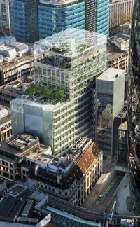
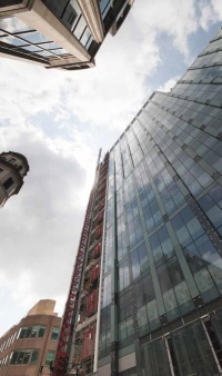
The new L-shaped building is located adjacent to the 41-storey Gherkin at 30 St Mary Axe and on a street with predominantly eight-storey structures.
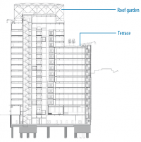
In order to fit comfortably into its surroundings, 6 Bevis Marks steps down from 16-storeys to 11-storeys towards the lower height buildings. Stepped roof terraces at levels 13 and 15 add some extra architectural interest, while both of these features are overlooked by the much larger rooftop sky garden.
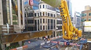
Constructing a new commercial development within the City of London always presents a number of challenges. When Skanska started on site in January 2012, the Olympic Games were on the horizon and this meant road closures in London, resulting in the delivery of large items such as cranes being restricted. “We had to keep a 3m wide lane open on Bevis Marks at all times,” says Andy Hankin, Skanska Project Director. “This meant our operations were severely restricted and so we had to come up with a method for utilising large cranes without closing the road.”
Skanska designed two 7.5m high steel trestles that were erected straddling the site and the road. A large 500t capacity mobile crane was then able to position two of its outriggers on top of the trestles, with the other two located within the permissible zone of the partially closed road. “The trestles, which were easily dismantled and re-erected, allowed us to use a crane to help install piling equipment, a tower crane and the large steel transfer beams,” explains Mr Field.

The mobile crane’s position was fixed, and its reach was limited by the nearby cores. This presented a problem when it came to lifting three large transfer beams. These beams, which span a ground floor loading bay and the structure’s reception represent the largest steel elements of the entire project and required a lot of planning to install.
The largest beam, installed above the loading bay, measures 15m long by 1,500mm deep with 1,000mm × 100mm flanges and twin 50mm webs. Weighing 38t the centre of gravity of this beam had to be shifted while it was lifted in order to avoid the core. Ten tonnes of kentiledge was bolted to the end of the beam, moving the centre of gravity by 450mm and allowing the beam to be successfully installed.
Two slightly smaller transfer beams for the roof of the entrance area, each 9m long and weighing 25t each, were lifted into place in a similar way.
All the transfer beams were successfully erected during one day, meaning partial road closure was kept to minimum.
Garden in the sky


The 6 Bevis Marks development is topped by an ETFE covered roof garden, which will be a dramatic addition to the local skyline.
Formed by a framework of CHS steel members the garden is open to the elements on two sides. The tubular steelwork wraps around two elevations of the structure, forming a curved profile and attaches to the main frame at level 11 on one side and level 15 on the other.
A total of eight 355mm diameter CHS column ‘trees’ support the steel frame at roof level. To form the framework up to seven rafters – typically 193mm diameter CHS members – are connected to each column.
“Each column tree is bespoke and the roof framework was trial erected at Tubecon’s fabrication yard, prior to being delivered to site, to make sure each piece fitted correctly,” explains Mr Field.
Site welding procedures to deal with potential hydrogen cracking
By Dr Richard Henderson (SCI)

A transfer beam on one of the upper floors of 6 Bevis Marks was erected in two halves which were site-welded together. This welded joint is clearly of major significance because a large proportion of the tensile capacity of the beam bottom flange must be developed. This is arguably the most important part of the joint as the top flange is in compression and the shear force near mid-span is likely to be small.
The actual process of welding on site is very little different from the equivalent workshop process but there are other factors which must be taken into account, the principal of which is that there are few fixed facilities or shelter available. Site welding also necessarily involves holding the parts in their correct positions and the welding is carried out in whatever orientation and location is determined by the joint.
Precipitation, wind and low temperatures can all have a substantial adverse effect on the quality of welds. Dew, condensation and atmospheric humidity are all sources of moisture which increase the amount of hydrogen in the weld pool and increase the risk of hydrogen cracking. A suitable weld procedure is required which controls the hydrogen input and allows greater opportunity for the hydrogen to diffuse out of the weld, just as for a shop weld, taking into account the carbon equivalent value of the steel.
The “combined thickness” of the joint is the sum of the element thicknesses 75 mm from the weld and the larger this value, the greater the heat sink and the higher the rate of cooling. A higher heat input is required to allow more time for hydrogen to diffuse out of the weld. The heat input is proportional to the product of the weld current and voltage, and inversely proportional to the welding speed. The weld preparation should also be chosen for simplicity: welding “downhand” (where the weld pool is lower than the electrode) is the easiest position. All these issues are specified in the weld procedure.
Welding consumables such as manual metal arc electrodes must be stored in dry conditions and only taken out when they are required. Some electrodes require baking and must be stored in heated quivers to lower the amount of hydrogen in the weld. Windy conditions can disturb or destroy the gas shielding around the arc which can affect both the mechanical properties and the appearance of the weld.
SCI publication P161; Guide to site welding gives detailed information on all these issues.
| Architect | Fletcher Priest Architects |
| Structural Engineer | Waterman Structures |
| Steelwork Contractor for main frame | William Hare |
| Steelwork Contractor for sky garden | Tubecon |
| Main Contractor | Skanska |
| Main Client | Bevis Marks Development |
| Development Manager | City Office Real Estate |