


Floor systems
The aim of this article is to highlight the requirements that may exist for a given building project, and indicate how these requirements should drive the designer towards the most appropriate, sustainable, potentially reusable and cost-effective choice of floor system.
The range of steel based floor systems is presented in general terms, with the advantages and disadvantages of each system identified so that these can be compared against the requirements of a given project. The article does not go into technical detail about the different types of composite, long span, and shallow floor solutions.

.JPG)
[top]What drives the choice of floor system?
Different buildings have different requirements, so not surprisingly there is no 'one size fits all' most appropriate solution. Clearly the requirements vary depending on the type of use, but there are also some more subtle issues to consider and these are highlighted below.
It should not be forgotten that when considering intended use, it may be appropriate to pay attention to a different use in the future - many steel solutions offer flexibility that can result in high levels of sustainability over the lifetime of a building.
[top]Simplicity and familiarity
As a rule of thumb designers should adopt the simplest solution that will meet the project requirements. Generally speaking the simplest solution will also be the most common, and familiarity will facilitate the design, fabrication and erection processes as no new learning is involved.
Within the context of steel floor systems, simple also means less labour and cost . For example, the simplest solution of a downstand solid web I-section beam as opposed to a truss means fewer structural elements, less fabrication , fewer surfaces to be fire protected and less time to design.
It is worth adding that this 'simple is best' philosophy also extends to frames as a whole - a simple braced frame will normally be a more economical solution than, say, a moment resisting frame.
[top]Speed of construction


(Image courtesy of Ayreshire Metals Ltd)
For some projects the need to reduce to a minimum the construction time (on site) may play a determining role. Indeed, time is often one of the key drivers for choosing a steel solution. The need for speed may be driven by, for example, fitting in with vacation breaks for educational buildings , or bringing in income (e.g. retail buildings). It can lead to consideration of options that minimise wet trades on site (use of precast floor units), minimise the number of crane lifts and provide working platforms during construction (profiled steel decking), and that do not require propping between floors.
[top]Service integration

The volume of services needed in a building is clearly a function of the end use - hospitals being an obvious example of a highly serviced building - and design philosophy adopted by the services engineer, e.g. air-conditioned, naturally ventilated, etc.
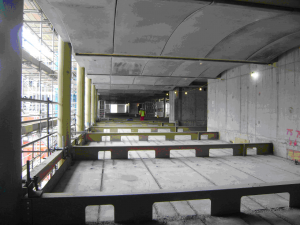
When a lot of service ducts are to be accommodated it may be beneficial to adopt a floor solution that provides a flat soffit in order to maximise the flexibility in routing these ducts beneath the structural floor. It will also be easy to remove and/or replace these ducts to meet future needs.
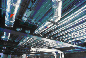
Solutions that provide a flat soffit may not suit the longer spans needed to facilitate a column-free adaptable floor area. An alternative in a building that is both highly serviced and requires long-span floors is to integrate the services within the beam depth (as shown to the right), so that the total depth of structural floor plus service zone is minimised.
[top]Need for adaptable space
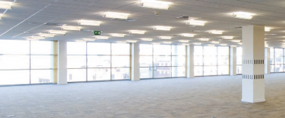

One of the long-recognised benefits of steel frame construction has been its ability to span significant distances. This is particularly true when composite solutions are adopted, given the efficiencies of that form of construction. This spanning ability allows the number of internal load bearing walls and columns to be minimised - open floor spaces can be created, or non load-bearing partitions (that are easily moved) used to form (temporary) individual areas. Adaptability may be more sustainable than deconstruction and reuse, for which steel is also suited. In recent years a number of steel framed office buildings have been reconfigured to provide residential units.
[top]Daylighting requirements
'Deep' floor plans may mean that, for example, office workers are a long way from natural lighting. Long span solutions may not then be the most appropriate solution for certain situations, where a short span design (for example using shallow floors ) with an internal atrium may provide a more appropriate internal environment. The designer must seek the best compromise.
[top]Aesthetics
If false ceilings are used then the aesthetics of the soffit of a given structural floor system are clearly irrelevant. However, clients may require exposed soffits, specified primarily so that the thermal mass of the floor is exposed. The soffit must also then be visually appealing. In some cases the presence of downstand beams interrupting the soffit may not be welcome, although it is also true that an expressed structure may be desired. A number of steel framed options may therefore be appropriate depending on specific requirements.
[top]Acoustics

The speed with which steel-framed buildings can be constructed, combined with excellent performance in service, was one of the reasons why steel frames with composite floors played such a central role in the boom in the multi-storey office market in the UK in the late 1980s and 1990s. When designers wished to transfer this technology to residential buildings some years later, it was recognised that possibly the biggest difference in requirements was issues associated with acoustics .
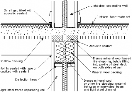
Good detailing is needed to avoid flanking issues, where sound travels around a barrier (such as a floor) by passing through an adjoining wall. An example, in accordance with the guidance provided in SCI P372, is shown below. The SCI has also developed an acoustic performance prediction tool for separating floors and walls to assist designers and architects.
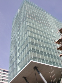
Numerous apartment buildings have been constructed using steel frames, with a combination of good detailing and proprietary products used for raised floors, providing the necessary levels of performance. Deansgate in Manchester was an early example of this 'technology transfer' (see right).

[top]Fire resistance
Fire resistance requirements depend on the use and height (number of storeys) of a building. Fire resistance periods between 60 minutes and 120 minutes are typical. The most common solution adopted to provide fire resistance is to protect the steel members so that they remain at a sufficiently low temperature (recognising that some loss of steel strength as temperature increases is acceptable as loads in fire are reduced compared to loading at ambient temperature). Intumescent coatings, (paint-like substances that char and expand with temperature to provide an insulation layer), are often used. If the steel elements are embedded in concrete this can provide the necessary insulation. Other options include board protection and the use of a cementitious spray.
Alternatively, when a 'fire engineering' approach is adopted the steel members are designed so that they are sufficiently strong, even when material strength has been lost due to exposure to fire, to resist the appropriate levels of loading. Extensive guidance, based on full scale fire testing of complete buildings, is available (SCI P375)
[top]Thermal mass

Provision of sufficient thermal mass is an important part of a low energy building solution. The mass provides a heat sink that absorbs heat during the day, and then in combination with natural ventilation the heat is purged during the cooler night time. Composite floor slabs may even be constructed with integral water ducts to aid this purging. It is important that the thermal mass is exposed - so false ceilings may be a problem, as is plasterboard attached with dabs to otherwise massive walls. Horizontal elements (floors) are much more effective at providing mass than vertical elements.
When deciding how much mass is needed it is important to consider the occupation pattern of a building. Massive structures can absorb a lot of heat, but they also provide thermal inertia when wanting a building to heat up rapidly. There is a common misconception that a very massive building is necessary to exploit the benefits of thermal mass.
[top]Floor stiffness
Stiffness is needed to ensure that a floor behaves correctly from a dynamic point of view, thereby assuring user comfort. This is a complex subject, as the real issue is how the floor responds (in terms of acceleration), which is a function of a number of variables including stiffness and the mass that is mobilised. The traditional approach, which is recognised as being crude, for designing a floor to respond acceptably is to check its natural frequency and compare that with a limiting value (which is a function of the floor mass). A more thorough approach is recommended, which often yields less conservative but satisfactory, results. See SCI P354.
A web-based Floor response calculator is available that allows designers to make an immediate assessment of the dynamic response of a floor solution. The software reports the results of approximately 19,000 arrangements of floor grid, loading and bay size, which have been investigated using finite element analysis. The results from this software provide an improved prediction of the dynamic response compared to the ‘manual method’ in SCI P354. The software may be used to examine complete floor plans or part floor plans, comparing alternative beam arrangements.
The required behaviour depends on the function for a given building/room. Some uses are less tolerant to floor movements (e.g. an operating theatre). Some uses (e.g. a gymnasium within an office building) are more likely to cause problems and warrant particular attention to avoid other building users being affected.
[top]Deconstruction

There has been considerable interest in the benefits of designing for deconstruction . The ability to dismantle a building and use the components again elsewhere is clearly attractive from a sustainability point of view, and steel lends itself to such a solution.
Research has been carried out on innovative shear studs, which allow composite slabs to be readily separated from the steel beams. Other initiatives involve the use of cross-laminated timber (CLT) used as a floor panel, used compositely with steel beams, but may be removed from the supporting steelwork as the building is deconstructed. Guidance on the recovery, testing and design of reused steelwork is available in SCI P427. Digital records of completed buildings, including information on the steel grade, impact properties and chemical composition should facilitate the efficient reuse of steel structures when a building reaches the end of its useful life.
[top]Cost
As noted above, unless project specific drivers suggest the adoption of a more sophisticated alternative, then the simplest solution should be chosen and this will normally prove to be the most cost effective.
Cost is a fundamental consideration in the selection of the frame and floor system. Late in 2016, the BCSA and Steel for Life commissioned AECOM to provide a series of building type specific cost comparisons for office, education, residential/mixed-use, retail and industrial buildings, based on actual buildings. The buildings selected were originally part of the Target Zero study conducted by a consortium of organisations including Tata Steel, AECOM, SCI, Cyril Sweet (now Currie & Brown) and BCSA in 2010 to provide guidance on the design and construction of sustainable, low and zero carbon buildings in the UK.
The cost comparisons presented in the ‘Costing Steelwork’ series update the cost models developed for the Target Zero project, and provide up-to-date costs for the alternative framing solutions considered for each of the five building types.
The cost comparison studies illustrate that for a range of building types, on a like for like basis steel frame and floor solutions are highly competitive. The studies also highlighted the importance of considering total building cost not just structural frame cost, as the choice of the structural frame and floor configuration will have associated impacts on many other elements, including the substructure, roof and external cladding.
[top]Benefits of different floor systems
[top]Slab options
[top]Composite slabs

Composite slabs, comprising lightly reinforced concrete cast on profiled steel decking, are an option whether the beams are downstand or integrated within the slab depth for a shallow floor form of construction. The slabs are normally reinforced using an upper layer of mesh and, occasionally, additional bars in the troughs (usually for longer periods of fire resistance and heavy loads). Fibre reinforcement may also be used. Spans of up to 4.5 m can be achieved using trapezoidal decking (80 mm deep). Some so-called deep decking profiles also exist (over 200 mm deep), that can span 6 m or so without propping during construction.
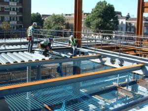
Composite slabs are an excellent choice when speed of construction is important. Bundles of decking are lifted into place on the steel structure, for distribution by hand. The number of crane lifts needed, when compared with the precast alternative, is greatly reduced. The ability to stack the pieces of decking into bundles also reduces transport time and costs.
During construction, once in place the decking provides other benefits in terms of acting as a working platform for storage of materials. When appropriately orientated and fixed to the steel beams it can restrain them against lateral torsional buckling. See SCI P300 .
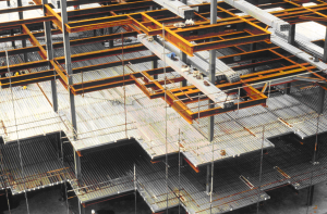
Composite floor systems
In the final state the ribs in the decking serve as void formers in the slab, thereby reducing the weight of floor construction with the knock-on benefits this can have. It is also possible to suspend services from the soffit of a composite slab, using anchors that are designed to slot into the decking profile.
A number of methods can be used for controlling the concrete level during construction. The concrete depth may be kept constant, or the upper surface may be kept level. Depending which of these is chosen the weight of concrete will vary, so it is important that the designer communicates clearly with the site team. See SCI AD410. Further guidance on the installation of metal decking is also available.
When an exposed soffit is required - to expose thermal mass - a thermally transparent suspended ceiling may be used. The additional surface area of the soffit created by the decking (as opposed to a flat concrete face) can be beneficial.
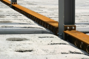
[top]Precast units
.jpg)
(Image courtesy of Severfield (Design & Build) Ltd.)
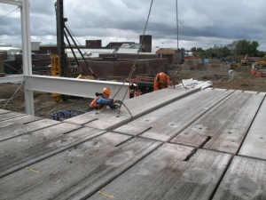
Precast concrete units may be used in conjunction with steel beams. The units may be solid or hollow-core, and with tapered or bluff ends. They are normally prestressed. The beams may also be structurally connected to the slab units to make them 'composite', provided specific detailing rules are satisfied to ensure that the steel section and concrete (in-situ topping plus the precast units) act together. SCI P401 gives further information on this.
Floors using precast units offer a number of benefits. The spanning ability of the units is such that the spacing of secondary beams can be increased (compared to when traditional decking profiles are used). The construction system is most efficient for column grids of approximately 9 m by 9 m. The units provide a flat soffit.
For semi-exposed applications, such as car parks, precast units may be a more durable alternative than steel decking (although with the correct detailing and coatings it is certainly possible to use decking in such applications).
Precast floors
[top]Downstand beam systems

The most common type of composite beam is one where a composite slab sits on top of a downstand beam, connected by the use of through deck welded shear studs. This form of construction offers a number of advantages - the decking acts as external reinforcement at the composite stage, and during the construction stage acts as formwork and a working platform. It may also provide lateral restraint to the beams during construction. The decking is lifted into place in bundles, which are then distributed across the floor area by hand. This dramatically reduces the crane lifts when compared with a precast based alternative.
Further guidance on practical aspects of decking placement may be found in the best practice guide SCI P300.
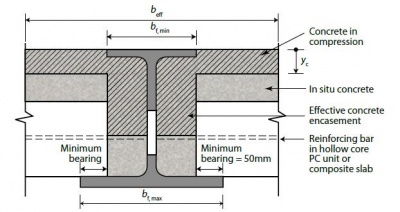
Another common type of composite beam is one where, as with a traditional non-composite steel framed solution, a precast concrete slab sits on top of the top flange of the steel beam. The effective span range for this type of solution is around 6 to 12 m, which therefore makes it a competitor to a number of concrete flooring options. Particular detailing is required for the shear connection when precast units are used, so that the body of the precast units can be mobilised as part of the concrete compression flange. See SCI P401 for more information.
[top]Long-span beams
A number of variations on the idea of downstand beams is available to meet long-span needs. The use of long span beams results in a range of benefits, including flexible, column free internal spaces, reduced foundation costs, and reduced erection times. Many long span solutions are also well adapted to facilitate the integration of services without increasing the overall floor depth.
[top]Shallow floors

(Image courtesy of Kloeckner Metals UK Westok)
Shallow floors offer a range of benefits such as minimising the overall height of a building for a given number of floors, or maximising the number of floors for a given height of building. Additionally, a flat soffit is achieved - there are none of the interruptions found with downstand beams - which gives complete freedom for the distribution of services below the floor. These benefits should be considered in the context of a given project to identify when they are most appropriate.
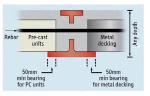
The shallowness of the floors is achieved by placing the slabs and beams within the same zone. This is achieved by using asymmetric steel beams with a wider bottom than top flange, which enables the slab to sit on the upper surface of the bottom flange with adequate bearing, rather than the upper surface of the top flange as found with downstand beams. The floor slab may be in the form of a precast concrete slab or a composite slab with metal decking (either shallow or deep decking may be used). An added benefit is that some forms of shallow floor construction inherently achieve composite interaction between the beams and slab, thereby enhancing structural efficiency.
A number of shallow floor solutions are available, including Ultra Shallow Floor Beams (USFB) from Kloeckner Westok, and ArcelorMittal's Slim Floor solutions.
USFB with precast hollocore slabs
(Image courtesy of Kloeckner Metals UK Westok)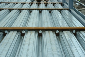
USFB with deep decking
(Image courtesy of Kloeckner Metals UK Westok)


Kloeckner Metals UK Westok’s USFB system comprises a shallow and asymmetric Westok cellular beam with reinforcement placed through the cells to anchor the slab to the beam. This simple detail provides a straightforward and cost-effective arrangement to prevent disproportionate collapse and is also used to resist torsion in the final condition. For composite slabs with metal decking the reinforcement is placed in the troughs of the metal decking. With hollowcore slabs, the reinforcement is placed in alternative cores of the precast unit. To restrain the top flange of the USFB in the Normal Stage, the insitu concrete should be cast flush with, or with at least 30 mm cover over, the top flange.

(Image courtesy of Kloeckner Metals UK Westok)
The USFB is manufactured from standard rolled sections, and is available in increments of 1 mm depth. They are typically 150-300 mm deep and are sized and designed using Westok’s freely available Cellbeam software package based on each individual project requirements and floor grids etc. The software carries out all of the necessary structural checks, including torsion checks in the Construction Stage. USFBs can economically span up to 10 m with structural depths that compare very favourably with R.C. flat slabs. As such, they are popular in many sectors, particularly Education, Commercial and Residential.
‘Plug Composite Action’ can be mobilised for USFBs, which has been demonstrated using full-scale laboratory testing, to further enhance the capacity of the section. To mobilise ‘Plug Composite Action’, the following detailing should be adopted:
- Composite slabs with metal decking: Concrete cast level with, or above, the top flange
- Precast units generally: Minimum 50 mm topping level with, or above the top flange
- Hollowcore units: Every 2nd core broken out and filled with concrete and reinforced through the cell
- Solid in-situ slabs: Concrete cast level with (or above) the top flange
[top]Resources
- SCI P287, Design of Composite Beams using Precast Concrete, 2003 (An updated Eurocode version of this publication, P401, is available from SCI)
- SCI P354, Design of Floors for Vibration. A New Approach, Revised Edition, 2009
- SCI P372, Acoustic Detailing for Steel Construction, 2008
- SCI P300, Composite Slabs and Beams using Steel Decking: Good Practice for Design and Construction, (3rd Edition), 2023
- SCI P375, Fire Resistance Design of Steel Framed Buildings, 2012
- SCI P401, Design of composite beams using precast concrete slabs in accordance with Eurocode 4, 2014
- SCI P427 Structural Steel Reuse, Assessment, testing and design principles, 2019
- SCI AD410, Pouring concrete to a constant thickness or to a constant plane, 2017
- SCI Acoustic performance prediction tool for separating floors and walls
- Floor response calculator
[top]See also
- Sustainability
- Thermal mass
- Recycling and reuse
- Cost of structural steelwork
- Cost comparison studies
- Fabrication
- Education buildings
- Healthcare buildings
- Residential and mixed-use buildings
- Retail buildings
- Multi-storey office buildings
- Car parks
- Acoustic performance of floors
- Junction details for acoustic performance
- Floor vibrations
- Steel construction products
- Braced frames
- Composite construction
- Long-span beams
- Structural fire resistance requirements
- Design of composite steel deck floors for fire