


Allowing for the effects of deformed frame geometry
This article introduces readers to methods of assessing the effects of deformed geometry on steel structures and allowing for them in their design. In some cases, the additional forces induced as the structure deflects are small enough to be ignored. In other cases, the forces are significant, and must be explicitly allowed for in design.
The Eurocodes ask designers to assess the effects of deformed geometry and introduces straightforward approaches to allow for the effects of inevitable frame imperfections.
[top]Sensitivity to effects of deformed geometry
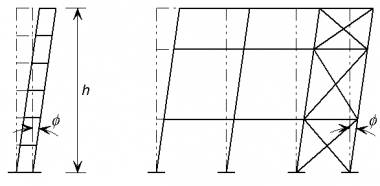
In the braced frame shown below the bracing extends due to axial tension, allowing the frame to move laterally, and producing an inclination in the columns, as shown. As the columns are now inclined, additional horizontal components of force must be resisted by the structure.

|

|
The horizontal components of the forces in the columns are proportional to the vertical loads, which demonstrates that frame stability is linked to vertical loads.
BS EN 1993-1-1[1], 5.3.2 states that, for frames that are sensitive to buckling, two types of imperfection should be considered:
It is important to note that 'sensitive to buckling in a sway mode' does not mean the same as needing to take into account second order effects due to the deformation of the structure. It means only that the geometrical deformation of the structure gives rise to additional effects in the members that must be taken into account in design. These additional effects may be only first order effects. If the geometrical deformation significantly affects the structural behaviour then second order effects also need to be considered.
[top]Sway imperfections

Permission to reproduce extracts from British Standards is granted by the British Standards Institution (BSI). No other use of this material is permitted. British Standards can be obtained in PDF or hard copy formats from the BSI online shop: http://shop.bsigroup.com or by contacting BSI Customer Services for hard copies only: Tel: +44 (0)20 8996 9001, Email: cservices@bsigroup.com
The global sway imperfections to be considered are shown in BS EN 1993-1-1[1].
The basic imperfection that is allowed for is an out-of-verticality Φ0 of 1/200. This allowance is greater than normally specified tolerances because it allows both for actual values exceeding specified limits and for residual effects such as lack of fit.
The design allowance in BS EN 1993-1-1[1], 5.3.2 is given by:
Φ = Φ0 αh αm = 1/200 αh αm
where αh is a reduction factor for the overall height and αm is a reduction factor which according to the Eurocode depends on the number of columns in a row. (For a detailed definition, see 5.3.2(3).) This presumes that every row has bracing. More generally αm should be calculated according to the number of columns stabilized by the bracing system - generally from several rows.
For simplicity, the value of Φ may conservatively be taken as 1/200, irrespective of the height and number of columns.

Sway imperfections may be neglected in structures, where, for each storey, the externally applied horizontal force exceeds 15% of the total vertical force. This is because in such an instance sway imperfections have little influence on sway deformation and amplification factor.
More details on imperfections for global frame analysis can be found in SCI P362.
Equivalent horizontal forces
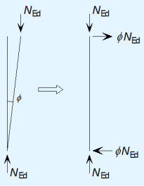
BS EN 1993-1-1[1] , 5.3.2(7) states that vertical sway imperfections may be replaced by systems of equivalent horizontal forces, introduced for each column. It is much easier to use equivalent horizontal forces than to introduce the geometric imperfection into the model. This is because:
- The imperfection must be tried in each direction to find the greater effect and it is easier to apply loads than to modify geometry
- Changing geometry can be difficult if the column bases are at different levels as the sway imperfection varies between columns.
According to BS EN 1993-1-1[1], Clause 5.3.2(7) the equivalent horizontal forces have the design value of ΦNEd at the top and bottom of each column, where NEd is the factored force in each column; the equivalent horizontal forces at each end are in opposite directions. For the design of the frame, it is much easier to consider the net equivalent force at each floor level. Thus an equivalent horizontal force equal to Φ times the total vertical design force applied at that level should be applied at each floor and roof level.
[top]Member bow imperfections
In a braced frame with nominally pinned joints , no allowance is needed in the global analysis for bow imperfections in members because they do not influence the global behaviour and are taken into account in the design of members through the use of buckling curves.
Should moment-resisting connections be assumed in the design of frames sensitive to second order effects, bow imperfections may need to be allowed for, as specified in BS EN 1993-1-1[1], Clause 5.3.2(6).
[top]Additional design cases for bracing systems
The bracing system must carry the externally applied loads, together with the equivalent horizontal forces. In addition, the bracing must be checked for two further design situations which are local to the floor level:
- Horizontal forces from floor diaphragms
- Forces due to imperfections at splices.
In both these design situations, the bracing system is checked locally (considering the storeys above and below) for the combination of the force due to external loads together with the forces due to either of the above imperfections. The equivalent horizontal forces modelled to account for frame sway are not included in either of these combinations. Only one imperfection needs to be considered at a time.
The horizontal forces to be considered are the accumulation of all the forces at the level being considered, divided amongst the bracing systems.
It is normal practice in the UK to check these forces without co-existent beam shears. The justification is that the probability of maximum beam shear plus maximum imperfections together with minimum connection resistance is beyond the design probability of the design code.
More details regarding bracing systems can be found in SCI P365 .
[top]Second order effects
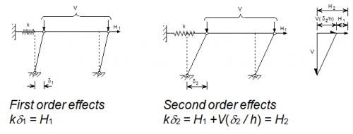

The sensitivity of a frame to second order effects may be illustrated simply by considering one 'bay' of a multi-storey building in simple construction, i.e. with pinned connections between beams and columns; the bay is restrained laterally by a spring representing the bracing system. First and second order displacements are illustrated in the figure below.
The equilibrium expression for the second order condition may be rearranged as:

Thus, it can be seen that if the stiffness k is large, there is very little amplification of the applied horizontal force; consideration of first order effects only would be adequate. On the other hand, if the value of vertical force tends toward a critical value Vcr ( = kh) then displacements and forces in the restraint tend toward infinity. The ratio Vcr/V, which may be expressed as a parameter αcr, is thus an indication of the second order amplification of displacements and forces in the bracing system due to second order effects. The amplifier is given by:

Note that according to BS EN 1993-1-1[1] both applied horizontal forces (e.g. due to wind) and any equivalent horizontal forces (representing sway imperfections) must be amplified.
[top]Criteria for the need to consider second order effects
BS EN 1993-1-1[1], 5.2.1(2) states that the effects of the deformed geometry of the structure (second order effects) need to be considered if the deformations significantly increase the forces in the structure or if the deformations significantly modify structural behaviour.
Sensitivity to effects of deformed geometry is measured by αcr and design standards indicate when αcr is large enough to mean that second order effects can be ignored.
[top]Calculation of αcr

For elastic global analysis, 5.2.1 says that the second order effects are significant if the parameter αcr < 10, where αcr is determined by first order analysis and is defined by the approximate expression:

where:
- HEd is the design value of the horizontal reaction at the bottom of the storey to the horizontal loads and the equivalent horizontal forces
- VEd is the total design vertical force on the structure on the bottom of the storey
- δh,Ed is the horizontal displacement at the top of the storey, relative to the bottom of the storey, when the frame is loaded with horizontal loads (e.g. wind) and equivalent horizontal forces which are applied at each floor level
- h is the storey height.
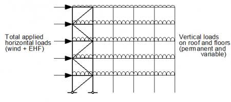
The criterion should be applied separately for each storey, for the condition where the full frame is loaded, as shown below. In most cases, the lowest storey will give the lowest value of αcr.
A Frame stability tool is available to assist with this calculation.
[top]Conditions for calculating αcr
When using Clause 5.2.1(4)B to calculate the value of αcr BS EN 1993-1-1[1] sets the requirement for the building to have a shallow roof slope. In the absence of more detailed information according to Note 1B a roof slope up to 26° may be taken as shallow.
Note 2B says that the above expression for αcr is only valid where the 'compression in the beams or rafters is not significant'. This limitation is intended principally for unbraced frames. In multi-storey braced frames the axial forces in the beams are normally small in relation to their flexural buckling resistance and thus the effect of axial force does not affect the sway stiffness of the frame.
[top]Calculation of αcr for portal frames
Expression 5.2 given in BS EN 1993-1-1[1] considers the lateral deflection under lateral loads. The basic expression must therefore be modified when applied to portal frames, since the lateral deflection at the column tops is generally dominated by vertical loads and thoughtless application of expression 5.2 will lead to erroneous results.
It is recommended that αcr be calculated based on the deflection due only to notional horizontal forces (NHF). The NHF should be taken as 1/200 of the factored vertical base reaction, and they should be applied in the same direction at eaves level, in the absence of any other loads.
The expression for αcr then becomes:

where:
- h is the height to eaves
- δNHF is the lateral deflection at the top of the column due to the NHF
Following guidance given in BS EN 1993-1-1[1], Note 2B to Clause 5.2.1(3), the above expression can be used only when the 'compression in the beams or rafters is not significant'.
Axial force in a rafter may be assumed to be significant if

A convenient way to express the limitation on the axial force is that the axial force is not significant if:
NEd ≤ 0.09Ncr
where:
- Ncr is the elastic critical buckling load for the complete span of the rafter pair, i.e.
![]()
- L is the developed length of the rafter pair from column to column, taken as span/Cos θ, where θ is the roof slope
If the limits are satisfied, then this expression may be used to calculate αcr. In most practical portal frames, the axial load in the rafter will be significant and this expression cannot be used.
When the axial force in the rafter is significant, an alternative method is used to calculate the measure of frame stability, defined as αcr,est. In many cases, this will be a conservative result. More accurate (higher) values of αcr will be obtained from software.
Taking account of base stiffness when performing the stability analysis for a portal frame with nominally pinned bases can increase the value of αcr significantly.
More details on αcr calculation for portal frames can be found in SCI P399 .
[top]Combinations of actions for global analysis
The determination of the value of αcr depends on design values of vertical and horizontal actions (loads) and thus depends on the relative magnitudes of these two groups of actions. This means that αcr must be determined separately for each combination of actions (notably for the different cases where wind load is the leading action and where the wind load is an accompanying action). It also means that a frame might not be sway sensitive in one combination yet sway sensitive in another.
[top]Allowing for second order effects
Where second order effects need to be allowed for, BS EN 1993-1-1[1], 5.2.2 spcifies that they may be allowed for by:
- An appropriate second-order analysis, taking into account the influence of the deformation of the structure.
- Using appropriate (increased) buckling lengths of members.
- Amplification of an elastic first order analysis using the initial geometry of the structure.
[top]Increased buckling lengths
The use of increased column buckling effective lengths is generally not recommended, simply because of the manual effort involved in calculating the effective length factors. However, if this option is chosen, effective length factors can be determined using a source of non-conflicting complementary information (NCCI), such as BS 5950 Annex E[2].
[top]Application of amplifier
Use of amplified first order effects is subject to the limitation that αcr ≥ 3 (if αcr is less than 3, second order analysis must be used).
The amplification factor is given in BS EN 1993-1-1[1], 5.2.2(5)B as:
The sway effects need to be amplified. In a braced frame, where the beam to column connections are pinned and thus do not contribute to lateral stiffness, the horizontal forces (including the equivalent horizontal forces) should be amplified. This will increase the axial forces in the bracing members and the forces in columns that are due to their function as part of the bracing system. In an unbraced frame, sway effects may arise from asymmetric loading or because the frame is asymmetric. BS 5950-1[2] clause 2.4.2.8 offers two alternative methods to identify sway effects.
[top]Second-order analysis
A range of second order analysis software is available. Use of any software will give results that are to some extent approximate, depending on the solution method employed, the types of second-order effects considered and the modelling assumptions. Frame imperfections may need to be modelled. The effects of deformed geometry (second-order effects) will be allowed for in the analysis. The effect of member imperfections and such things as residual stresses are allowed for if verifying members in accordance with the rules in Section 6 of BS EN 1993-1-1[1].
[top]References
- ↑ 1.00 1.01 1.02 1.03 1.04 1.05 1.06 1.07 1.08 1.09 1.10 1.11 1.12 1.13 BS EN 1993-1-1:2005+A1:2014, Eurocode 3: Design of steel structures. General rules and rules for buildings, BSI
- ↑ 2.0 2.1 BS 5950-1:2000 Structural use of steelwork in building. Code of practice for design - Rolled and welded sections, Annex E Effective lengths of compression members in continuous structures, BSI
[top]Resources
- SCI P399 Design of steel portal frame buildings to Eurocode 3, 2015
- SCI P397 Elastic Design of Single-span Steel Portal Frame Buildings to Eurocode 3, 2013
- SCI P362 Steel Building Design: Concise Eurocodes, 2009
- SCI P365 Steel Building Design: Medium Rise Braced Frames, 2009
- Frame stability tool