


Design of composite steel deck floors for fire
A composite steel deck floor is designed in bending as either a series of simply supported spans or a continuous slab. Strength in fire is ensured by the inclusion of mesh (sometimes called fabric) or fibre reinforcement. Mesh reinforcement can be that present in ordinary room temperature design; it may not be necessary to add reinforcement solely for the fire condition.


[top]Assessment of composite steel deck floors with mesh reinforcement
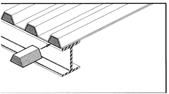
Composite steel deck floors consist of a profiled steel deck with a concrete topping. Included in the concrete is some light welded mesh reinforcement which acts to control cracking, to resist longitudinal shear and, in the case of fire, to act as tensile reinforcement. Indentations in the profiled deck allow the concrete and steel to bond and share load. Composite action between the supporting beams and the concrete is created by welding shear studs through the deck onto the top flange of the beam.


In the fire condition, practice amongst designers is to make the conservative assumption that the steel deck makes no contribution to overall strength. The deck does however play an important part in maintaining integrity and insulation. It acts as a diaphragm preventing the passage of flame and hot gases, as a shield reducing the flow of heat into the concrete and it controls spalling. It is not normally necessary to fire protect the exposed soffit of the deck.
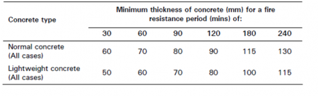
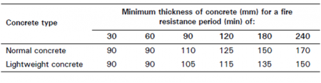
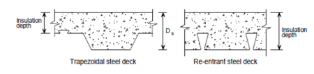
BS 5950 Part 8[2] provides a table of recommended concrete thicknesses to satisfy the insulation criterion for common periods of fire resistance. The minimum thickness of concrete required to satisfy the insulation requirements is shown for trapezoidal and re-entrant decks when subjected to a BS 476 Part 20[1] fire test. The insulation depth depends on the type of profile, and it is the concrete cover to the main crest of the deck for trapezoidal profiles and the full slab depth for re-entrant profiles.
In fire the reinforcement becomes effective and the floor behaves as a reinforced concrete slab with the loads being resisted by the bending action. Catenary action may develop away from the edges of the floor with the reinforcement then acting in direct tension rather than bending. Slab failure occurs when the reinforcement yields.
Two methods are available for the design of composite steel deck floors designed to BS 5950 Part 4[3] for fire. Both are described in the Steel Construction Institute guide P056. These are the fire engineering and the simplified method.
In the fire engineering method it is assumed that the plastic moment capacity of the floor can be developed at elevated temperatures and that redistribution of moments takes place in continuous members. The hogging and sagging moment capacities of the slab are calculated via temperature distributions based on extensive fire testing covering fire resistance periods of up to four hours. These are then compared with free bending moments for both internal and end spans at the required fire resistance period and the design adjusted as necessary to ensure that the floors meet the required criteria.
The simple method consists of placing a single layer of standard welded fabric reinforcement in the concrete. Guidance is available on maximum loads, reinforcement size and position and also allowable span and support conditions. In practice the simplified method will almost invariably lead to the use of less reinforcement than the fire engineering method. The fire engineered method however allows greater flexibility in reinforcement layout, loading and achievable fire resistance times.
Lightweight concrete is a better insulator and thus loses strength less rapidly in fire than normal weight concrete. Hence lightweight concrete floors tend to be thinner than normal weight alternatives.
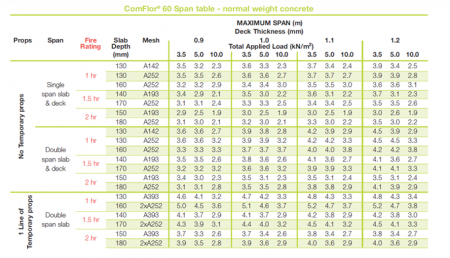
Most decking manufacturers’ data on slab details for fire resistance will be based on the simple method although the engineered method is occasionally used. This is usually signified by the presence of bottom reinforcing bars in the slab. Most steel decking manufacturers also provide software for the design of floors using their products and also produce literature with quick reference information.

For Eurocode design, BS EN 1994-1-2[4] contains a simplified method for calculating the design moment of resistance of composite steel deck floors in fire. It should be noted that, in the National Annex[5], Informative Annex D, Model for the calculation of the fire resistance of unprotected composite slabs exposed to fire beneath the slab according to the standard temperature-time curve is not applicable in the UK. This is because many UK decking profiles are outside the limits of the field of application.
In the United Kingdom, this problem has been solved by the publication of Non-conflicting complimentary information (NCCI) in the form of PN005c-GB. Decking manufacturers produce their own guidance based on this NCCI.
[top]Assessment of composite steel deck floors with fibre reinforcement
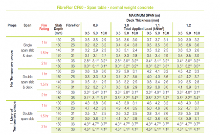

Fibre reinforcement consists of short fibres made from steel, polypropylene or a combination of both, which are mixed into the concrete prior to placement. Under controlled circumstances, fibres may be substituted for the mesh (fabric) reinforcement. Use of fibre reinforcement results in a three dimensional reinforced concrete composite slab. The performance of fibre reinforcement is verified empirically, specifically for fire resistance and for longitudinal shear transfer, using the same testing regimes that are used to validate the use of traditional reinforcement within composite steel deck floors. Decking manufacturers’ software generally includes allowance for fibre reinforcement, as does their product literature. Fibre reinforced composite steel deck floors are not a generic product. A specific type and dosage of fibres must be used according to each fibre manufacturer’s specification for the particular deck, and other deck or fibre types cannot be substituted.
The process by which fibre reinforced composite steel deck floors are to be designed for fire to the Eurocodes has not yet been established. PN005c-GB states that The fire design of composite slabs constructed with fibre reinforced concrete needs specialist calibration and software, the theory of which is outside the scope of PN005c-GB. SCI should be contacted for further information.
[top]Filling of voids
Research has shown that filling the gaps between the raised parts of the deck profile and the beam top flange in composite steel deck construction is not always necessary. The upper flange of a composite beam is so close to the plastic neutral axis that it makes little contribution to the bending strength of the member as a whole. Thus, the temperature of the upper flange can often be allowed to increase, with a corresponding decrease in its strength without significantly adversely affecting the capacity of the composite system.
Gaps under decking with dovetail profiles (sometimes called re-entrant profiles) can remain unfilled for all fire resistance periods. The larger voids which occur under trapezoidal profiles can be left open in many instances for fire ratings up to 90 minutes, although some increase to the thickness of fire protection applied to the rest of the beam may be necessary. More informaton and detailed background information is provided by the Association for Specialist Fire Protection (ASFP)[6].
Designers should take care that gaps are filled where the beam forms part of the compartment wall to ensure the integrity of the compartment. In the rare case where non-composite steel deck construction is used, the gaps must always be filled if trapezoidal decking is used.
Cellular beams require separate consideration. Advice is provided by the ASFP[6].
- Filling of voids
Preformed fillers are available for filling the voids in steel deck construction where required.
Image courtesy of Firetherm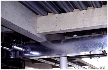
Installed void fillers


[top]References
- ↑ 1.0 1.1 1.2 BS 476-20: 1987, Fire tests on building materials and structures. Method for determination of the fire resistance of elements of construction (general principles). BSI
- ↑ BS 5950-8: 1993, Structural use of steelwork in buildings. Code of practice for fire resistant design. BSI
- ↑ 3.0 3.1 3.2 BS 5950-4: 1994, Structural use of steelwork in building. Code of practice for design of composite slabs with profiled steel sheeting. BSI
- ↑ BS EN 1994-1-2: 2005+A1:2014, Eurocode 4. Design of composite steel and concrete structures. General rules. Structural fire design. BSI
- ↑ NA to BS EN 1994-1-2: 2005. UK National Annex to Eurocode 4. Design of composite steel and concrete structures, General rules. Structural fire design. BSI
- ↑ 6.0 6.1 Fire protection for structural steel in buildings (5th ed). Association for Specialist Fire Protection
[top]Resources
- Steel construction - Fire Protection supplement, 2013
- SCI P056 The fire resistance of composite floors with steel decking, 1991
- NCCI: Fire resistance design of composite slabs. PN005c-GB. SCI
[top]See also
- Design using structural fire standards
- Fire protecting structural steelwork
- Fire testing
- Structural fire engineering
- Structural fire resistance requirements