


Ladder deck composite bridges
Ladder deck bridges are one of the most common types of medium span composite bridge in the UK. This article provides a description of the features of this type of bridge and introduces some of the structural design considerations.

[top]Configuration of a ladder deck bridge
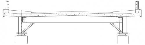
In a ladder deck bridge, there are two main longitudinal and the deck slab is supported on cross girders that span transversely between the main girders - the slab then spans longitudinally between the cross girders. This arrangement is referred to as ‘ladder deck’ construction, because of the plan configuration of the steelwork, which resembles the stringers and rungs of a ladder. A typical cross section of a ladder deck bridge is shown below. The arrangement with two main girders is appropriate (and economic) for a bridge width up to that for a dual two lane carriageway. Wider decks can be carried on a pair of ladder decks.
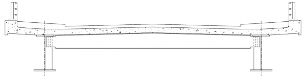

The main girders and cross girders are both provided with shear connectors to develop composite action. Cross girders are usually connected to the main girders by bolting; intermediate transverse web stiffeners are provided at each cross girder connection. Most ladder deck bridges are designed with uniform depth main girders but variable depth girders can be used. Examples of uniform depth and variable depth ladder decks are shown below.
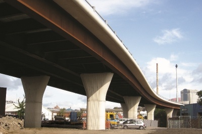
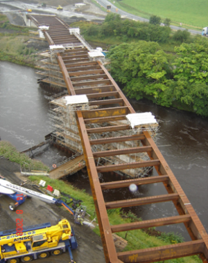
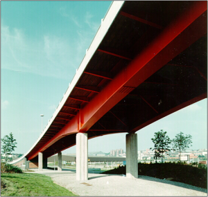
Ladder deck viaduct with uniform depth main girders
Holmfield Viaducts, A1(M) Darrington to Dishforth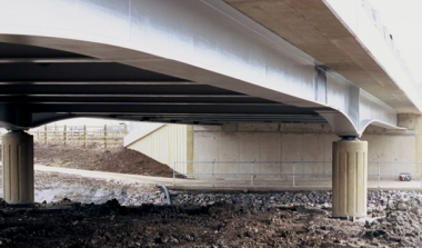
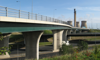
Ladder deck bridge with haunched main girders
Semmington Brook Bridge,
(Image courtesy of Arup)


Where the deck is wide (more than about 22m), for example when a dual three lane carriageway is carried, two adjacent ladder deck arrangements can be used. In such cases, the deck slab can be continuous across all four main girders or separate slabs may be provided, one on each pair of girders. Where the slab is continuous, it spans transversely between the innermost girders (which are thus limited to a spacing of about 3.5 m between them). Where separate slabs are provided, each deck cantilevers transversely and some form of joint may be required in the central reserve (see CD 377
[1]for requirements relating to gaps between decks).
[top]Main girders
The main longitudinal girders are almost always fabricated from plate; the heaviest rolled sections are unlikely to be sufficient, even for modest spans. Because there are only two webs, the web plate is thicker than it would be in a multi-girder arrangement; the web slenderness is lower and it is usually possible to develop the necessary shear resistance in the webs without use of web stiffening, other than that at the cross girders. With longer spans, the size of the flanges, particularly the bottom flange, is likely to be quite large (in both width and thickness). Designers should check the availability of suitable plate material at an early stage, with particular attention to the toughness grade.
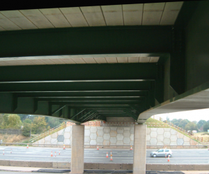
[top]Cross girders

Haydon Bridge Bypass
(Image courtesy of Severfield (UK) Ltd.)
Cross girders are usually spaced at about 3.5m centres, to suit a slab thickness of about 250mm. They are connected to the transverse web stiffeners on the main girders.
For a simple two or three lane bridge, where the main girders are 7–10m apart, rolled sections (universal beams) may be sufficient for structural purposes, but plate girders are more likely to be used. Where there is a camber to the road surface (for example, with a two lane single carriageway, as shown above) the top flange of a plate girder can follow the cross falls, allowing the use of a uniform thickness of both slab and surfacing. The bottom flange would normally be straight. If rolled sections cross girders were used, either the sections would have to be cambered (which adds to fabrication cost), or the slab or surfacing must be tapered in thickness to provide the falls.
Where there is superelevation of the road surface, one main girder is arranged higher than the other and the cross girder depth is usually constant.
Cross girders are usually unstiffened and unbraced but long cross girders may require bracing for the construction condition (typically, channel bracing between pairs of girders at their mid-span).
[top]Intermediate cross girders in sagging moment regions
Intermediate cross girders effectively act as simply supported beams in carrying the loading from the slab. The end moments, due to interaction with the main girders, are very small in relation to the strength of the cross girders, which can thus be designed as simply supported beams. However, the end moments may be large enough to influence the design of the cross girders to main girder connection.
In the composite condition, the cross girders in the sagging moment regions of the main girders are required to provide lateral restraint to the main girders bottom flanges only where the main girders are curved in plan or where lateral loads from vehicle impact on the soffit are to be resisted. The cross girders provide restraint through U frame action (see further description below).
The cross girders also provide out-of-plane restraint to the slab where it is in compression; the stiffness of the cross girders and the slenderness of the slab both need to be considered.
During construction, the cross girders provide torsional restraint to the main girders, both as restraint to lateral torsional buckling and, for curved main girders, in resisting the couple generated by the opposing ‘radial’ forces in the tension and compression flanges.
[top]Intermediate cross girders in hogging moment regions

In the hogging moment regions of the main girders, adjacent to internal supports, the intermediate cross girders are required to provide lateral restraint to the bottom flanges of the main girders, which are in compression. This restraint is provided through the ‘inverted U frames’ formed by the cross girders and web stiffeners to which they are attached. The connections between main and cross girders therefore need to transmit restraint moments and the frame needs to be stiff. If the cross girders are significantly shallower than the main girders, knee bracing or haunched cross girders may be needed, both to stiffen the frame and to reduce moments that need to be transmitted through the cross/main girder connections; see the descriptions of such arrangements for support cross girders, below.
[top]Cross girders at internal supports (pier diaphragms)
At the internal supports of continuous spans, the cross girders are very often deeper than the intermediate cross girders, providing a stiffer and stronger ‘pier diaphragm’, with bolted connections that can transfer the larger restraint forces that occur at the supports. The cross girder should not be quite as deep as the main girder, to avoid conflict with, and direct connection to, the bottom flange of the main girder.


As an alternative to using a deeper cross girder, knee bracing or a haunched cross girder can be provided, as shown below. This will stiffen the frame and reduce moments that need to be transmitted through the cross/main girder connections and may be advantageous if services or access ways are connected to the soffits of the cross girders along the length of the bridge. In practice, intermediate knee bracing is rarely provided – it is cheaper to use a deeper cross girder. Haunched cross girders are an even more expensive detail and a fabricator should be consulted before selecting this option.


[top]End supports
With non-integral construction, support diaphragms similar to those at intermediate supports are used. They provide an effective support to the end of the deck slab and to the expansion joint. Where the end supports are skew to the bridge axis, the diaphragms may act as trimmer girders.
With integral bridges, the end diaphragm acts as a cross girder or trimmer girder.
[top]Integral crossheads at internal supports
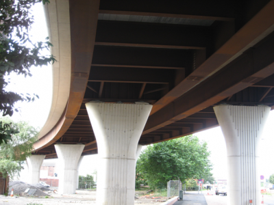

Supports are sometimes provided ‘inboard’ of the main girders, under the pier diaphragms, rather than directly under the main girders. The diaphragms are then more substantial and are often referred to as ‘integral crossheads’. There may be good reasons for such an arrangement, particularly when it is difficult to provide support under one of the girders on a skew bridge, but it does add considerably to the fabrication and erection cost. If the main girders are haunched, such an arrangement, with no direct support under the most heavily loaded elements, is thought by many people to look rather unsettling. An example of an integral crosshead is shown below.
Note that if the main girders of the arrangement shown below were haunched, stiffeners would be required on both sides of the main girder webs and the web/flange connections would need to be designed for the tensile load due to vertical components of the forces in the inclined main girder flange.
Where longitudinal forces are transferred at the bearings, additional bracing to the bottom flange may be needed (to avoid plan bending of that flange).


[top]Cantilever girders

Festival Park Bridge, Stoke
(Image Courtesy of Cass Hayward LLP)
For normal lengths of deck cantilevered outside the main girders (up to about 2m), cantilever girders are not needed; the slab will cantilever transversely, as it does with multi-girder decks.
Steel cantiever girder allow longer deck cantilevers to be provided but the main reason for considering them would be to avoid the need for cantilevered formwork. With cantilever girders, permanent formwork can be used across the full width of the deck. The provision of cantilever girders leads to the requirement for moment continuity with the cross girders. This adds significantly to fabrication cost. Also, it is difficult to achieve good alignment at the tips of long cantilevers and this too adds to cost. A cross section of a ladder deck with cantilever girders is shown below.


[top]Reasons for choosing a ladder deck
Clearly, the most common and strongest reason for choosing a ladder deck form of construction is economy but other factors such as appearance (the reduction in number of columns, avoidance of leaf piers, suitability for plan curvature) and the ability to adapt to a wide range of support arrangements (i.e. where positions for intermediate supports are severely constrained) are also influential.
There are several ways in which economy can be achieved – in the amount and cost of the steelwork, in the ease and speed of construction and in the greater use of prefabrication.
The particular economic advantages that are common to most forms of ladder deck construction are:
- A reduced tonnage of steel, relative to multi-girder construction (although fabrication costs per tonne may be a little higher)
- The use of permanent formwork (which is mainly of regular sizes) which both speeds construction and reduces the reliance on labour in-situ work such as formwork construction
- The suitability for large slab pours (there is a reduced need for staged construction)
- The suitability for use of ‘clip-on’ cantilever falsework (there is torsional restraint of the main girder at every cross girder location and this provides a stiff support to the cantilever).
Whether a ladder deck configuration is more economic overall usually depends on very scheme-specific factors, such as access for erection and erection equipment, facility for arranging temporary supports, construction programme and traffic management. The designer should therefore consult widely at an early stage in the initial design process. Most bridge construction in the UK currently takes place under partnering arrangements and thus access to steelwork contractors and main contractors should be readily available to the designer. In the absence of a partnering arrangement, designers should at least discuss the options with a steelwork contractor at an early stage.
[top]Case studies

[top]References
[top]Resources
- Hendy, C.R.; Iles, D.C. (2015) Steel Bridge Group: Guidance Notes on best practice in steel bridge construction (6th Issue). (P185). SCI
- Iles, D.C. (2010) Composite highway bridge design. (P356 including corrigendum, 2014). SCI
- Iles, D.C. (2010) Composite highway bridge design: Worked examples. (P357 including corrigendum, 2014). SCI
- Iles, D.C. (2012) Design of composite highway bridges curved in plan. (P393). SCI
- Iles, D.C. (2012) Determining the buckling resistance of steel and composite bridge structures. (ED008). SCI
- Iles, D.C. (2015) Determining design displacements for bridge movement bearings. (P406). SCI
- Steel Bridges: A practical approach to design for efficient fabrication and construction, 2010, (Publication no. 51/10), BCSA,
- Guide to the Erection of Steel Bridges, 2005, (Publication no. 38/05), BCSA
- Carbon footprint tool for steel composite highway bridges
- Preliminary steel bridge design charts:
- Chart finder
- Spreadsheet tool
- User manual
- All three of which can be found on the BCSA web site
[top]See also
- Multi-girder composite bridges
- Integral bridges
- Bridges - initial design
- Modelling and analysis of beam bridges
- Design of beams in composite bridges
- Shear connection in composite bridge beams
- Fatigue design of bridges
- Bracing systems
- Stiffeners
- Connections in bridges
- Bridge articulation and bearing specification
- Plan curvature in bridges
- Skew bridges
- Design for steel bridge construction