


Design for half-through construction
The structural configuration of a half-through bridge generally creates a linear rectangular U–shaped trough, the vertical legs being the main girders and the horizontal being the bridge deck. Design of such bridges requires consideration of the interaction between the transversely spanning action of the deck and the longitudinal spanning of the main beams. The interaction is generally referred to as U-frame action.This article introduces the design considerations for half-through bridges, with references to design standards where appropriate.


[top]Structural behaviour
While the structural behaviour is essentially a simple hierarchical progress of slab spanning between cross girders, cross girders spanning between main girders and main girders spanning between supports, the key structural ‘element’ that requires special design consideration is the ‘U-frame’ that is created by a cross girder and the two vertical stiffeners to which it is connected. The need for frames is to provide intermediate lateral restraint to the top flanges, which are in compression. Such intermediate restraint is able to constrain the buckling mode of the top flanges, as shown below left.
The restraint provided by each ‘U-frame’ depends on the three components – cross girder, vertical stiffeners and the connections between cross girder and main girder. The restraint can be expressed in in terms of a flexibility under unit lateral load, as shown below right.
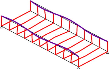
Constrained buckling mode of top flanges
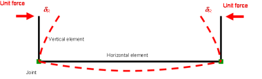
Flexibility of a 'U-frame'


The influence of this flexible restraint on the design of the main girder is discussed below.
Global analysis to determine load effects is usually carried out using a grillage model. For railway bridges it is usually sufficient to have a line of nodes along the rail lines, as well as along the main girder, and across every cross girder for closely spaced cross girders (up to 1500mm spacing). For highway bridges, a finer mesh will be needed, similar to that for ladder deck bridges.
[top]Design basis
[top]Loading

The loading arrangement to give maximum effects in the main girders is easily determined. A line beam analysis would give adequate results. Evaluation of the effects on the cross girder and their connections require more detailed consideration. For a railway bridge, an ‘axle load’ (one of the 250 kN point loads in the Load Model 71 of BS EN 1991-2[1]) should be positioned over the cross girder being considered and the Uniformly Distributed Load (UDL) should be present on both sides. The effects induced in the cross girder by this loading depends on the stiffnesses of the slab and cross girder and is best determined by the grillage model.
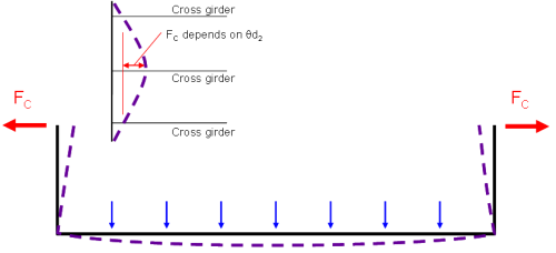
Maximum end moments on a cross girder occur when one cross girder is more heavily loaded than its neighbours. Under direct load, a cross girder bends and the uprights of the ‘U-frame’ want to lean inwards, but they are partially restrained by the top flange, spanning between the adjacent ‘U-frames’, as illustrated right.
The loading that gives the most onerous value of force Fc is with all the loading to one side of the cross girder, as shown below.


Load effects on highway bridge cross girders also depend on the stiffness of the ‘U-frames’ and similar dispositions of loading apply.
[top]Governing criteria
The design must consider the criteria of :
- Fatigue
- Deflection performance
- Strength
For highway bridges, design is usually controlled by strength, with some details controlled by fatigue. For railway bridges, fatigue and deformation performance are much more significant and strength may be a lesser consideration (because a design that satisfies the other criteria, will usually be strong enough).
Most half-through bridges are replacements for an existing structure, or on the line of an existing railway or road. Buildability is often the most significant factor in choosing the structural configuration. For guidance on the considerations needed for railway bridges, refer to SCI P318.
[top]Fatigue and deformation performance
[top]Fatigue

The principles of fatigue design are the same for half-through bridges as for other forms of bridge, namely:
- Determine the loading events and their frequency
- Classify the detail under consideration, in terms of its performance under cyclic loading
- Determine the fatigue life of the detail under the design loading history
The cross girders in half-through bridges have a particularly onerous loading cycle, since most of the load is a variable action (traffic load) and the effects for each loading event are a high proportion of the maximum design value. This is particularly true for railway bridges, where Load Model 71 is used for both Ultimate Limit State (ULS) and fatigue loading, and there are four ‘axles’ for each loading event. The onerous nature of the loading applies also to the connections to the main girder.
With onerous loading cycles, there is a strong incentive to use the ‘best’ fatigue details, but there are certain details where only lower class details can be used, notably:
- Doubler plate terminations
- Cross girder connections.
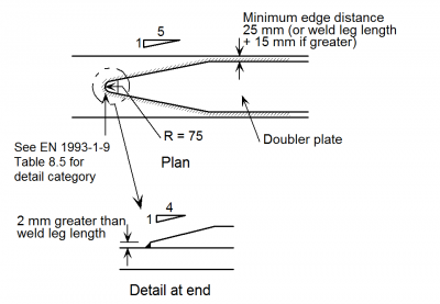
A typical doubler plate detail is shown above right. At its ends, the doubler plate is tapered in plan and in elevation, to smooth the stress flow as much as possible, but a detail category 36 (in accordance with BS EN 1993-1-9[2]) is inevitable for thick flanges. The fillet weld attaching the doubler must be checked as a detail category 80 in shear, for the stress flow transferred.
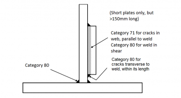
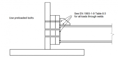
At cross girder connections, there is often a plate welded onto the face of the web, as shown below. Discontinuous plates (i.e. a separate ‘patch plate’ at the end of each cross girder) introduce detail categories 80 and 71 into the web. Shear is transferred through category 80 fillet welds. If the plate were continuous, the detail on the web would be category 100, but the shear transfer through the fillet weld is still category 80. The bolted connections use preloaded bolts and provided that the preload is maintained under fatigue loading there is no special concern. The connections at the ends of the cross girders introduce further category 80 in shear; a suitable size fillet weld must be chosen.
- Cross girder end connection details


Cross girders are usually rolled sections and free from welding in their midspan regions (except where stud connectors are welded on top). The fatigue classification is therefore good. However, it is best to avoid any welded attachments (such as to support services) in these midspan regions as they would introduce lower classes into regions that experience a particularly onerous fatigue loading.
[top]Deformation performance
The comfort and safety of railway traffic is sensitive to the deformation performance of bridges and although half-through bridges are not intrinsically more susceptible, the structural configuration and high ratio of live to dead load mean that deformation performance is a prime consideration. Two of the most common aspects that need to be checked are twist and gradient at the end of the span. The effects are illustrated below. Deflection limits for railway bridges are given in Annex A of BS EN 1990[3] and these are adopted in GCGN5612[4], although there is a correction / clarification that for the calculation of vertical deformation, the effects from railway traffic should be multiplied by the dynamic factor (Φ) as well as the load classification factor (∝).
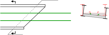
Twist in a skew span
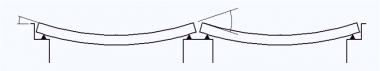
Change of gradient between adjacent spans under live load


[top]Design resistance of main girders
[top]Effective section
It is usual to neglect the contribution of the deck to the resistance of the main girders at ULS but interaction must be considered at the Servicibility Limit State (SLS) – notably in determining shear flow between deck and main girders near the ends of the span and in determining crack widths in the concrete slab.
[top]Bending resistance
The main consideration in determining the resistance of the main girders is the stability of the top flange in compression. As mentioned above, restraint is provided by the ‘U-frame’; it is therefore necessary to consider their effectiveness in preventing buckling of the top flange.
The buckling behaviour of the top flange of a simply supported half-through bridge is actually a distortional buckling phenomenon (the deflected shape of the ‘U-frame’ is a distortion of the cross section) but BS EN 1993-2[5] only recognises lateral torsional buckling slenderness and the rules for determining the parameter ![]() need to be followed.
need to be followed.
Clause 6.3.4.2 of BS EN 1993-2[5] offers a method that can be applied to lengths between effective lateral restrains and with flexible intermediate restraints. This method is based on a beam-on-elastic-foundation (BEF) model. This underlying BEF model is of an infinitely long beam/strut subject to axial load and restrained at intervals by lateral springs, as shown diagrammatically below.

However, the clause rules cannot be used for flexible end restraints (which is the likely situation, since end ‘U-frame’ will not be ‘rigid’). To remedy this deficiency, PD 6695-2[6] (Section 9) provides an adjustment to the m parameter in clause 6.3.4.2.
Alternatively, elastic critical buckling resistance can be determined by a finite element buckling analysis and this will lead to the determination of design resistance of the main girder.
[top]Toughness
BS EN 1993-1-10[7] gives rules for limiting thickness of elements to avoid brittle fracture and these rules are amplified by the UK National Annex[8] and PD 6695-1-10[9]. In most cases, these rules lead to the selection of ‘ordinary’ sub grades of J2 or K2 quality. However, when doubler plates are terminated on a tension flange, the detail is ‘severe’ (i.e. the adjustment of reference temperature is −30°C) and, coupled with significant tensile stress and the use of thick material, would require the use of the highest toughness quality (ML or NL) – and even those sub-grades may not be tough enough. Doublers on tension flanges should therefore be taken the whole length of the span in a simply supported bridge or into a compressive region in a multiple span bridge.
[top]Design resistance of cross girders
The cross girders usually act compositely with the slab, or with a steel deck plate. For composite girders, adequate shear connection must be provided. In most cases, the deck will be in tension due to global effects and bond should not be relied upon to provide the connection. Reinforcement passed through holes in the web or shear connectors on top of the girders will achieve the necessary connection. Since the cross girders are predominantly in sagging bending (there are only small end restraint moments arising from ‘U-frame’ effects) there are no lateral torsional buckling considerations, even when the slab or plate is on top of the girder (rather than encasing or partly encasing it).
[top]Best practice details
In the drafting of SCI P318, a range of preferred details was drawn up, based on advice from designers and fabricators. Comments were given on their suitability in terms of fatigue endurance, fabrication, installation and durability. Refer to that publication for detailed advice.
An example of a preferred detail is shown below.


[top]References
- ↑ BS EN 1991-2:2003. Eurocode 1: Actions on structures. Traffic loads on bridges. BSI
- ↑ BS EN 1993-1-9:2005. Eurocode 3: Design of steel structures. Fatigue. BSI
- ↑ BS EN 1990:2002+A1:2005. Eurocode: Basis of structural design. BSI
- ↑ Guidance on Loading Requirements for the Design of Railway Structures. Railway Group Standard GCGN5612 (Issue 2, 2018). RSSB.
- ↑ 5.0 5.1 BS EN 1993-2:2006. Eurocode 3: Design of steel structures. Steel bridges. BSI
- ↑ PD 6695-2:2008+A1:2012. Recommendations for the design of bridges to BS EN 1993. BSI
- ↑ BS EN 1993-1-10:2005. Eurocode 3: Design of steel structures. Material toughness and through-thickness properties. BSI
- ↑ NA to BS EN 1993-1-10:2005. UK National Annex to Eurocode 3: Design of steel structures. Material toughness and through-thickness properties. BSI
- ↑ PD 6695-1-10:2009 Recommendations for the design of structures to BS EN 1993-1-10. BSI
[top]Resources
- Iles, D.C. (2004) Design guide for steel railway bridges (P318) SCI
- Steel Bridges: A practical approach to design for efficient fabrication and construction. (51/10). BCSA
- Hendy, C.R.; Cooper, M.C. (2025) Steel Bridge Group: Guidance Notes on best practice in steel bridge construction (7th Issue). (P185). SCI
[top]See also
- Half-through bridges
- Material selection and product specification
- Modelling and analysis of beam bridges
- Shear connection in composite bridge beams
- Fatigue design of bridges
- Stiffeners
- Connections in bridges
- Bridge articulation and bearing specification
- Skew bridges
- Design for steel bridge construction
- Design of steel footbridges