


Tied-arch bridges
Masonry arch bridges, which have a very long history, and more recent landmark bridges, such as Sydney Harbour Bridge in Australia and the Tyne Bridge in England, are all ‘thrust arches’ and rely on horizontal restraint from the foundations. In many cases, such ‘external’ restraint is not feasible or practical but it can be replaced by a tie between the ends of the arch, thus creating a ‘tied-arch’. This article describes the features and behaviour of tied-arch structures.
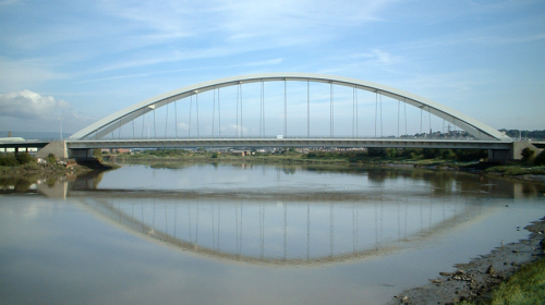

(Image courtesy of Mabey Bridge Ltd.)
[top]How a tied-arch works
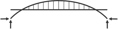

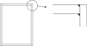
Thrust arches rely on horizontal restraint from the foundations, as shown right. The vertical and horizontal reactions resolve into a force along the arch members – the horizontal component is of significant magnitude.
This will be the most satisfactory solution when the arch bears onto good foundation material such as competent rock. The ends of the arches are normally pinned. However, rock is not always available and so a thrust arch will not be the most economic solution at these locations, as the horizontal reactions lead to heavy uneconomic foundations.
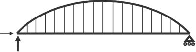

The tied-arch offers a solution when it can be arranged that the deck is at such a level that it can carry the horizontal force as a tie member, as shown below.
The tied-arch is sometimes referred to as a bowstring arch.
By taking the arch thrust through the tie member, the primary requirement for the substructure reduces to only carrying vertical loads. It can be seen that one end will still require a longitudinal restraint to carry wind, braking, acceleration and skidding forces, and that the other end is permitted to move longitudinally.
[top]Overall structural behaviour
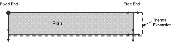
Looking at the diagram above, it can be seen that a tied-arch is really just a simply supported beam. The arch is held longitudinally at one end, with the other end free to expand or contract under varying temperatures.
If a load is placed on the deck, it is transferred to the arch via the hangers, as the global stiffness of the arch is greater than the bending stiffness of the deck. This creates thrust in the arch, which is balanced by tension in the tie beam. The arch will deform downwards, and it will try to spread its feet, but this is limited by having to stretch the tie beam. Hence there will be an outward movement at the free end.


[top]Articulation
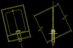
The deck is conventionally articulated using the principles mentioned above. An example is given in the figure below. In this case global longitudinal loads on the bridge are shared between both bearings at the fixed end.

[top]Related structural forms
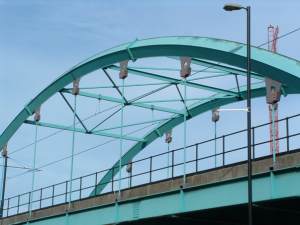
Most tied-arch bridges have vertical hangers, although in some bridges the hangers are arranged to criss-cross. In this case, as with the tied arch with vertical hangers, the hangers can only act in tension, but the criss-crossed hangers will transfer some global shear along the span. If the hangers are increased in size, and are triangulated, then the tied arch becomes a bowstring truss. There is full shear transfer through the triangulated web members.
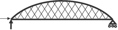
Tied arch with cross hangers
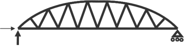
Bowstring truss


[top]Span Range
As a rough guide, typical spans for tied-arches carrying highways is in the range 75m to 250m. For railways, the range would be 50m to 200m. As always, there are exceptions to these rules.
[top]Aesthetics
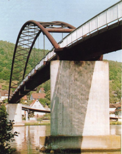

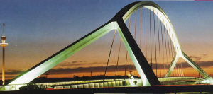
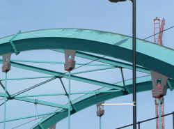
The tied-arch form is one that is open to many interpretations, and with careful conceptual imagination and attention to detailing can produce stunning and beautiful structures. Tied-arch bridges can be created with a single arch member, two independent arches or two arches braced together, In the latter case, a more graceful bridge can often be created by leaning the arches towards each other and this has the structural advantage of reducing the span of the inter arch bracing.
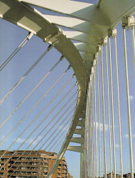
Single arch member
Barquetta, Seville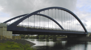
Independent arches
Toome Bypass, Northern Ireland


With inclined arches for road bridges, care needs to be taken to ensure that there is sufficient headroom between the carriageway and the arch and this may lead to a slightly wider structure.
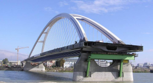
Inclined arches
Košická Bridge, Bratislava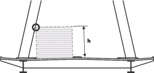
Cross section through tied arch with inclined arch planes


The limits for clearance gauge are defined by the highway authority; for highway bridges this is given in CD 127[1]. Additionally, where the clearance is less than a given limit, accidental actions due to vehicular collision may need to be considered in design, According to the National Annex to BS EN 1991-1-7[2], impact force must be considered if the clearance is less than 5.7m. Above 5.7m, no impact forces need be considered.
Note that h is measured normal to the road surface.
However, given the lack of redundancy, the designer should also consider the robustness of the design in the event of a vehicle impact, but this is likely to be important for smaller spans where the arch rib will be of small proportions.
For longer spans (or where the arches are tall) it may be feasible for the lean of the arches to be such that they merge into one element.
[top]Components and choice of materials


The arch is primarily a compression member and so a closed box section will be the most efficient. There is a choice of whether the arch should be stiffened longitudinally or not. The balance to be considered is one between the loss of efficiency when using ‘thin’ plates (b/t >24), and the additional fabrication cost of stiffened panels.
To minimise future internal maintenance, arches are frequently fabricated from weathering steel, painting the exterior, but leaving the interior unpainted.
Bracing between the arches can take a number of forms, and can even be omitted in small to medium spans. Tubes are commonly used, and are generally too small for man access. They can either be sealed, or vented into the arch boxes with provision for drainage. Note that hot rolled hollow sections are not available in weathering steel.
- Forms of arch bracing
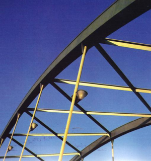
X-braced
Rigidly connected cross-beam


K-braced

Unbraced arches


The tie is primarily in tension, and so can be a variety of shapes. Often an “I” section is chosen as being most economic, but this complicates the connection with the base of the arch. A normal carbon steel would usually be selected for the tie beam.
- Tie beams

I-section tie beam
Box-section tie beam (for bridge with inclined hanger planes)


There is a wide choice for hangers. The simplest is the round bar, such as the Macalloy system. Bars are available up to 100 mm diameter. However, although they are made from a quality steel, this is of a much lower strength than the cable options, and so hangers must be provided at closer centres. The most compact choice is to use either rope, spiral strand or locked coil strand. Otherwise there are a number of proprietary systems that are used for cable stayed bridges that can be readily adapted for arches.
The bridge deck can be a steel orthotropic deck or concrete. Generally the simplest means of support for these is a ladder deck with cross girders. The main issue with concrete is the problem of it interacting with the tension developed in the tie beams. This is discussed further below.
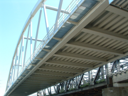
Orthotropic steel deck for a tied arch bridge
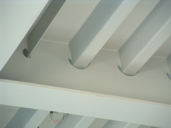
Orthotropic steel deck for a tied arch bridge
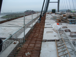
Concrete deck (precast units on ladder deck, before in-situ concreting)


[top]Global design
[top]Arch Shape
A parabolic arch is the best shape for structural efficiency because, under uniform load there should just be axial forces in the arch members. However, the presence of the tie beam contributes stiffness to the system and this means means that there are some moments, especially around the arch springings. A circular arch will always have greater bending moments in the arch members.
[top]Influence lines
Although the tied arch is essentially just a simple span, the influence lines of some of the elements are worth examining. It is obvious that maximum axial forces are generated when the whole span is loaded. However, maximum bending will occur with just part of the span loaded. A typical influence line for bending in the arch is given below left. Note that there are both positive and negative parts. The influence line for a vertical hanger usually comprises a single positive peak as shown below right.
- Influence lines
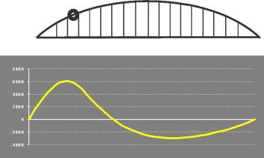
Influence line for axial force in arch member
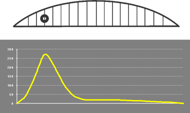
Influence line for force in a hanger


[top]Loading
Dead load effects will normally comprise a large proportion of the design stresses for main elements, and it becomes very important to allow fully for the erection method. This particularly applies to bending in the arch; for the tie beam, the locked in bending moment can be controlled by adjusting the hanger lengths.
The application of traffic load is straightforward, but there will be a variety of loaded lengths and positions of tandem axles and special vehicles must be chosen to suit the influence lines.
Wind loading on the arch is a significant effect and is usually critical for design of the inter arch bracing. Aerodynamic instabilities are unlikely to be a problem due to the inherent stiffness and high natural frequency of the arch. However, for longer spans and when in doubt, wind tunnel tests should be considered.
Depending on the type and nature of barriers between the highway and hangers, it may be necessary to design the bridge for the accidental loss of a hanger. The criterion is to prevent progressive collapse of the whole span. This is an accidental design situation and thus is normally considered with characteristic values of permanent and variable loads. However, it will be necessary to allow for the routine replacement of hangers. As this will be a planned action, it is usually possible to reduce traffic load for this transient design situation through traffic management (e.g. no abnormal loads, contraflow on opposite carriageway).
[top]Analysis
In general, a linear elastic analysis is sufficient for all the design, with the possible exception of the resistance of the arch to lateral buckling. If the arches are fully braced together, then the rules for buckling resistance of members between restraints can be applied is a straightforward manner. If a less complete system is envisaged, then a geometric non-linear buckling or eigenvalue analysis will be required to establish elastic critical buckling values and modes. Rules for determining slenderness to out-of plane buckling are given in Annex D of BS EN 1993-2[3].
[top]Detail Design
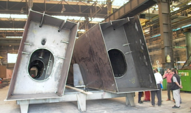
[top]Arch/tie connection
This is likely to be the most complex area for fabrication, particularly if the arch is inclined. The arrangement of plating is generally intuitive and confirmed by some local finite element modelling. In addition to dealing with force and moment transfer, careful consideration must be given to how the pieces can be fabricated , so as to achieve an efficient, but cost-effective solution.
[top]Hangers
Design rules for tension components are given in BS EN 1993-1-11[4]. As a rule of thumb, it is convenient to size the cables under SLS loading, limiting tensile stresses to 45% of breaking load. Proprietary system manufacturers can provide data on various forms of rope, strand and bar.
Under accidental loss of a hanger, adjacent remaining hangers are permitted to work at higher stress levels. Cable anchorages (sockets etc) and their fixings are usually sized such that their strength exceeds the breaking load of the cable. Local steelwork details should be designed with robustness in mind.
Fatigue loading will need to be considered using data from manufacturer’s tests.
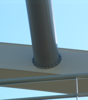
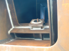
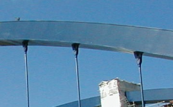
Hangers can be either terminated inside the arch or below it. This is a preference decision as there are pros and cons for both. Internal connections will be neatest, but requires installation and subsequent inspection and maintenance inside a confined space (assuming it is large enough to enter). External connections will require specialist access equipment such as cherry pickers, use of which may involve unacceptable disruption to traffic.
Hangers must be adjustable to allow for geometrical tolerances between arch and tie, and for initial stressing and subsequent adjustment. Allowance may need to be made for space to accommodate, and reactions from, jacking equipment.
Guidance on the specification of tension bar components is available in Guidance Note 4.05
- Hanger connection (internal)
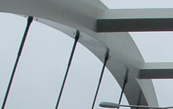


- Hanger connection (external)


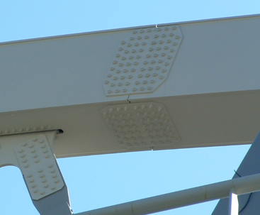
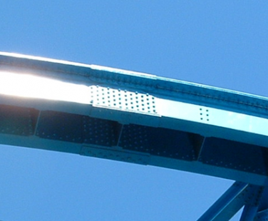
[top]Splices
Splices in the arch may of course be made by either bolting or welding. In the UK bolting is favoured for site splices in normal bridgework. However, welding should also be considered on visual grounds for arch splices. For the tie beam, welding is efficient in terms of design as there is no loss in section from bolt holes.
- Bolted splices in arch members


[top]Concrete deck
In the addition to the usual requirements for designing a concrete deck, it is also necessary to consider the potential high tensile forces (and associated high tensile strains) in the tie beam and the concrete deck. The issues that arise are:
- High tensile strains leading to cracking of concrete
- Need for high level of shear connection between steel and concrete
- Uncertainty of load sharing of tie force between tie beam and concrete/reinforcement
Some useful guidance on this subject is available[5].
The construction sequence of the whole bridge and especially the concrete deck needs careful consideration to ensure compatibility with design assumptions.
A concrete deck may need to be cast in longitudinal strips to avoid critical half span loading cases.
To minimise the above difficulties precast concrete panels may be used, stitching them together once they have all been installed. Nevertheless, careful detailing will be required to produce a trouble free design.
[top]Durable Design and Maintenance
Modern paint systems are very durable and can have a long life. With large areas of steel located above the deck, thought must be given as to how rainfall will run off and where it may collect. For example, rain will run down hangers and may collect at socket mouths. Even if neoprene gaiters are provided to keep water out, drainage paths must be provided to prevent accumulation of water.
The use of weathering steel for box elements is a useful measure, with benefits for health and safety, as no painting will be required internally. If box elements are large enough to permit access, then manholes must be provided. These need to be sized to permit evacuation of someone on a stretcher – those used for potholing rescue are the most compact.
Access within an arch can be problematic due to the constantly changing angle, internal stiffeners, and possibly hanger terminations. Options available include step irons, grab rails, high friction walking surface and fall arrest lines.
[top]Fabrication and Erection
[top]Precamber
In a normal beam and slab bridge, precamber (allowance for permanent deformation) is applied to the steel beams to shape them such that when full dead load is applied their deflected shape is the intended profile. This is achieved by cutting the web plate accordingly to deal with these bending effects.
The situation is likely to be more complicated in a tied arch. For example, the elastic stretch of the tie beam during construction needs to be accounted for; this can be achieved by fabricating it short by the appropriate amount. In a 200m span bridge this may amount to some 125mm. However, as it is possible through hanger adjustment to minimise dead load moments, it is not necessary to apply any precamber against dead load moments.
The arch may present many more challenges, which will be strongly influenced by the erection procedure. If sizeable lengths are lifted and joined to other sections, their self weight deflection may be significant. The 60m long central section of the Usk Bridge deflected about 250 mm when it was lifted and supported for splicing by its ends. Also its ends kicked out by some 40 mm. Other parts of the erection sequence will contribute deflections to the whole arch, such as installation of hangers, deck concrete, finishes etc. If the arch is inclined, then in-plane and out-of-plane components will need to be resolved. Finally, overall length compatibility must be maintained to correspond with the tie beam extension.
[top]Fabrication

In most cases, the deck will comprise I sections, which can be readily fabricated using “T&I” machines. The tie beam to arch joint can often be a complex fabrication with the requirement for large butt welds if thick plates are being used. If in doubt advice should be sought from a fabricator. It may be necessary to specify plate with improved through thickness properties where large cruciform welds are required.
An arch box is usually a simple fabrication comprising four plates joined along their edges. As shears are generally quite low in the arch, the required size of these welds is small. It is normal to have an internal fillet weld plus an external part penetration weld.
To maintain squareness, the fabricator may wish to add ring frames at the ends of the fabricated sections. Butt welds may be required to join arch and tie beam units together. When used in the arch careful design and welding sequence may be required as there is often high restraint leading to the possibility of weld cracking. Again, advice may be sought from a fabricator.
[top]Erection
Erection methodologies will depend on many factors including bridge size, type, obstacle to be crossed and other site conditions. Issues to be considered may include:
- Availability of site – are possessions required for rail, road or navigable waterway?
- Available craneage and location of cranes for lifts. This will determine the weight and sizes of the pieces to be lifted.
- Does the bridge have to be built in its final position, or adjacent and then lifted, floated, or launched into position?
- Availability/feasibility of temporary supports. As a tied-arch is a single span, intermediate supports will be required if not built in one piece.
[top]Case studies


[top]References
- ↑ CD 127 Cross-sections and headroom, The Design Manual for Roads and Bridges. TSO
- ↑ NA+A1:2014 to BS EN 1991-1-7:2006+A1:2014. UK National Annex to Eurocode 1. Actions on structures. Accidental actions. BSI
- ↑ BS EN 1993-2:2006, Eurocode 3. Design of steel structures. Steel bridges, BSI
- ↑ BS EN 1993-1-11:2006. Eurocode 3. Design of steel structures. Design of structures with tension components. BSI
- ↑ Johnson, R.P. (2003) Analyses of a composite bowstring truss with tension stiffening. Proceedings of the Institution of Civil Engineers. Bridge Engineering Vol 156, Issue BE2
[top]Resources
[top]See also
- Ladder deck composite bridges
- Material selection and product specification
- Weathering steel
- Shear connection in composite bridge beams
- Fatigue design of bridges
- Bracing systems
- Stiffeners
- Connections in bridges
- Bridge articulation and bearing specification
- Design for steel bridge construction
- Corrosion protection
- Welding